作者: 刘, 子豪

1) Mobile device:

You can adjust the text size by changing the display ratio.

Tap [More] → [Select Map] → [Display Ratio] to set the desired ratio.

2) PC:

The font size is fixed on the PC version of QubiMap. You can choose [Switch Map] > [Large Font Mode] to show the map in large font mode.

When you export a shape as an image, the default blue background color that fills the shape may affect the image clarity or obscure the objects that need to be displayed. The following two methods are available to remove the background color:

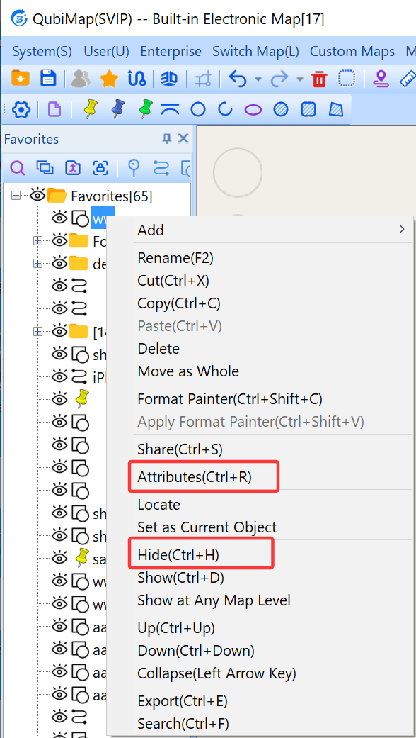
  1. Hide the shape. After you set the shape to hidden, the eye icon before this shape name changes to img. Then, go to the shape settings and export the shape as an image.

image-20260720141511870

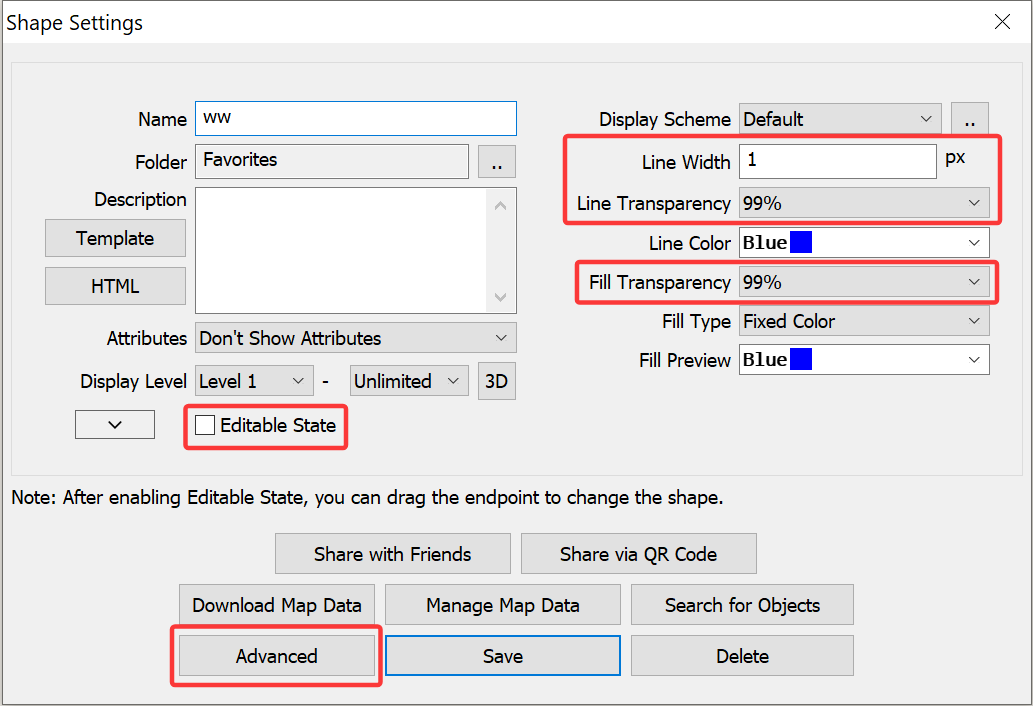
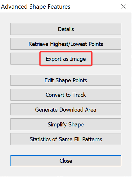
  1. In the [Shape Settings] dialog box, set the line and fill transparency to 99%, and unselect [Editable State] to make the shape uneditable. Then, click [Advanced] → [Export as Image] to export the shape as an image.

image-20260720141952631

image-20260720142040338

QubiMap supports browsing maps in 3D mode. In this mode, you can also customize the placemark display style to achieve the 3D effect of placemark text.

1) PC

Open the QubiMap software and click the 3D button to enter 3D mode.

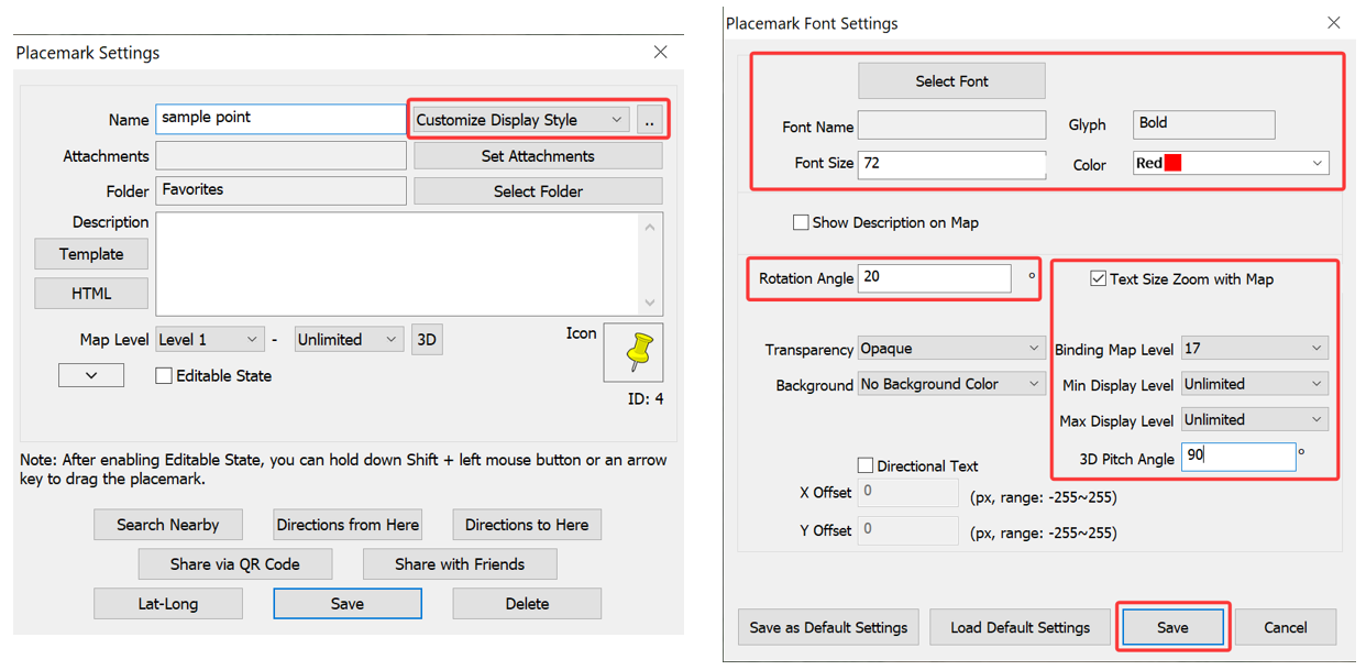
Double-click the placemark on the map to go to the [Placemark Settings] dialog box. Select [Customize Display Style] from the drop-down list next to the placemark name (text), and click the [..] button on the right. In the [Placemark Font Settings] dialog box that appears, set the parameters as needed, and click [Save].

image-20260713164941772

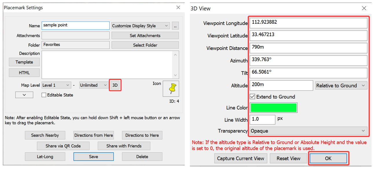
In the [Placemark Settings] dialog box, click [3D]. In the [3D View] dialog box, set the parameters as needed and click [OK]. Then, click [Save].

image-20260713165345970

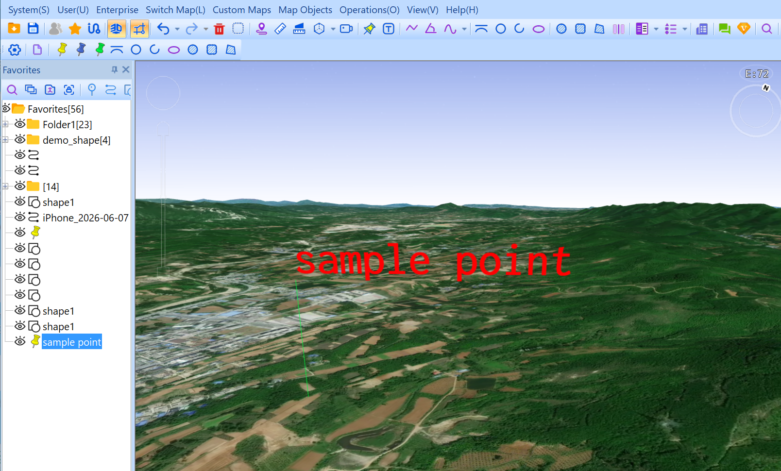
The placemark text is vividly demonstrated on the map, as shown in the following figure:

image-20260713165624840

2) Mobile device

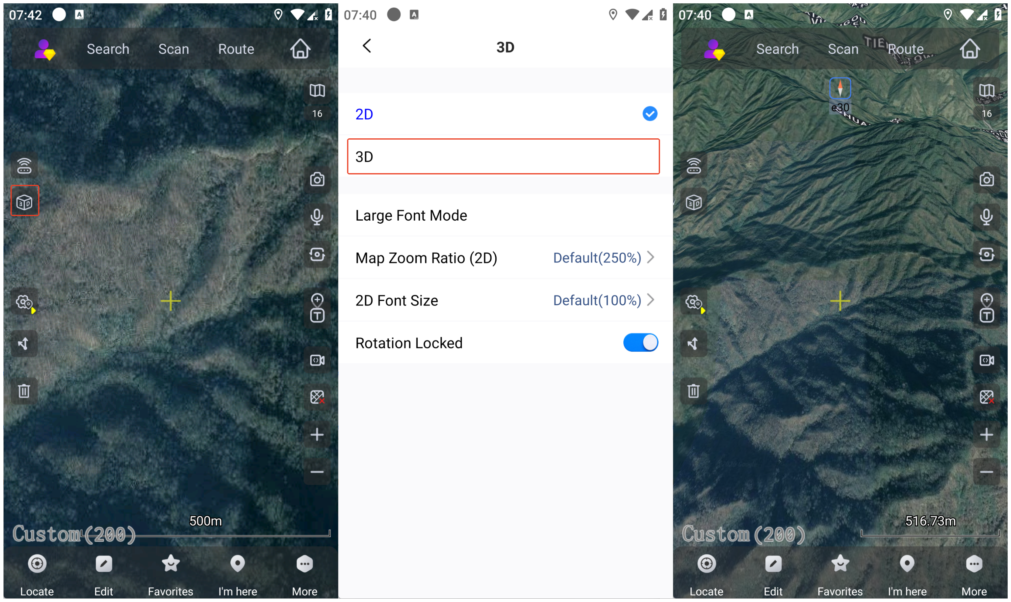
Open the QubiMap app and tap the 3D button on the main UI to enter 3D mode.

dasd

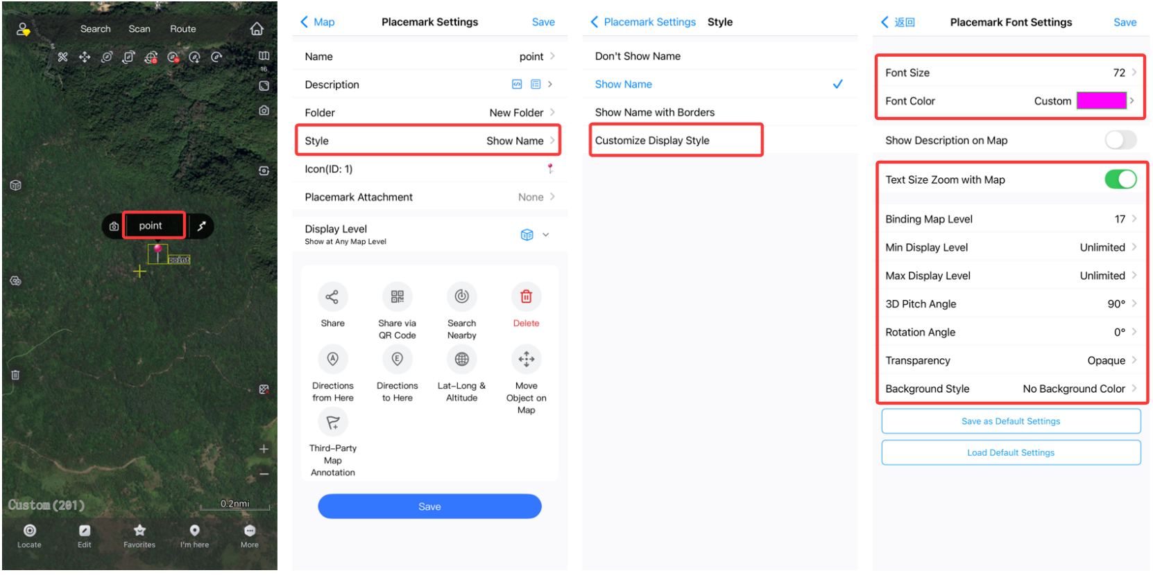
Double-tap the placemark on the map to go to the [Placemark Settings] page. Select [Customize Display Style] from the [Style] list. On the [Placemark Font Settings] page that appears, set the parameters as needed, and tap [Save].

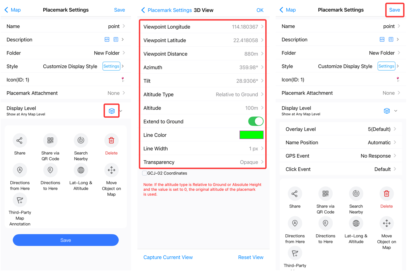
image-20260714101952727On the [Placemark Settings] page, tap the [3D] icon. On the [3D View] page, set the parameters as needed and tap [OK]. Then, tap [Save].

image-20260714102453286

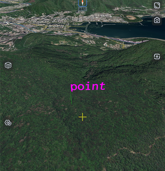
The placemark text is vividly demonstrated on the map, as shown in the following figure:

image-20260714102646513

QubiMap supports customizing fill types for shapes. You can use a single color, gradient, image pattern, or CAD pattern to fill a shape. This article describes how to use an image pattern to fill a shape.

1) PC

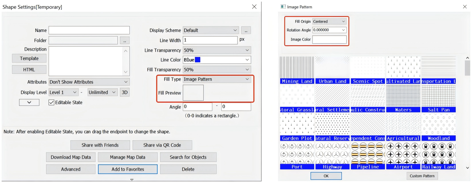
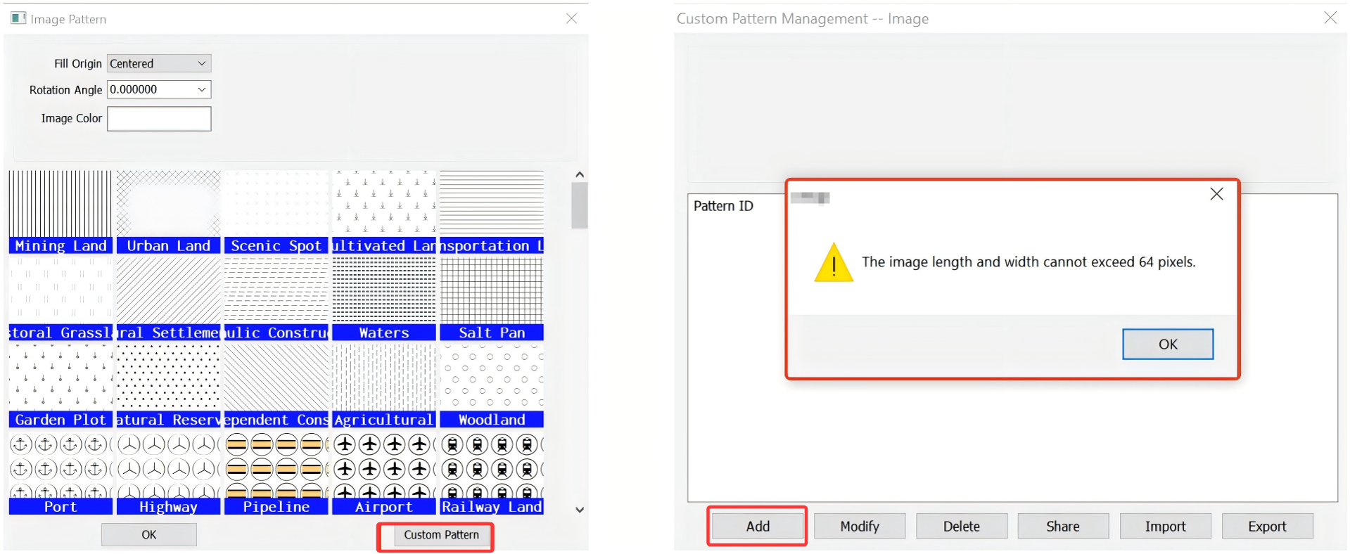
Draw a the map on the map. In the [Shape Settings] dialog box that appears, select [Image Pattern] from the [Fill Type] drop-down list, and click [Fill Preview].

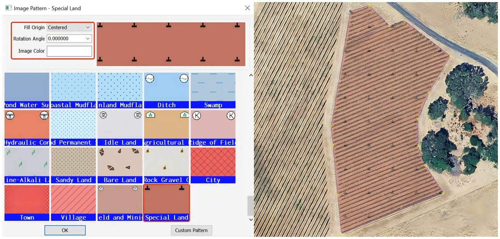
QubiMap provides commonly used patterns. You can select an image pattern and modify the attributes of the pattern as needed.

Fill Origin: The default value is [Centered]. You can also select [Custom] to set the origin.

Rotation Angle: After you set this value, the pattern on the right changes accordingly.

Image Color: Set the color of the image.

You can also click [Custom Pattern] to add custom image patterns. Note that the image length and width cannot exceed 64 pixels.

image-20260716093517425

After you add the image patterns, close the [Custom Pattern Management–CAD] dialog box. In the [Image Pattern] dialog box, you can select a custom CAD pattern to fill the shape. Then, click [OK]. In the [Shape Settings] dialog box, click [Add to Favorites] to add the shape to your favorites.

2) Mobile device

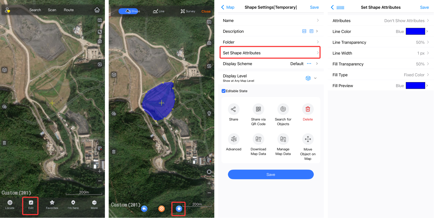
On the main UI, tap [Edit] → [Shape] to draw a shape. Tap the Favorites button at the bottom to go to the [Shape Settings] page, and then tap [Set Shape Attributes].

image-20260716093636571

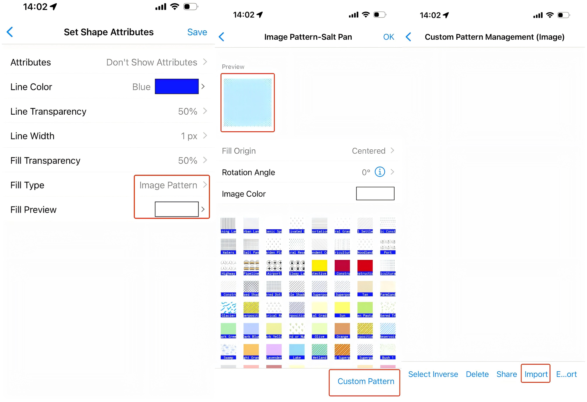
Set [Fill Type] to [Image Pattern], and tap [Fill Preview] to go to the [Image Pattern] page. You can select an image pattern and modify the attributes of the pattern as needed. Note that the [Fill Origin] parameter is set to [Centered] by default and cannot be modified on the mobile device. To add a custom image pattern, you must import the corresponding file.

After configuration, tap [OK] → [Save] → [Save] to add the shape to your favorites.

QubiMap (PC version) supports batch renaming of subfiles, placemarks, tracks, shapes, and routes in the favorites. You can specify prefixes, suffixes, and serial numbers for the selected names, or replace part of text in the names by content or position. In this example, multiple placemarks are renamed at a time.

1) Specify prefixes, suffixes, and serial numbers for multiple names

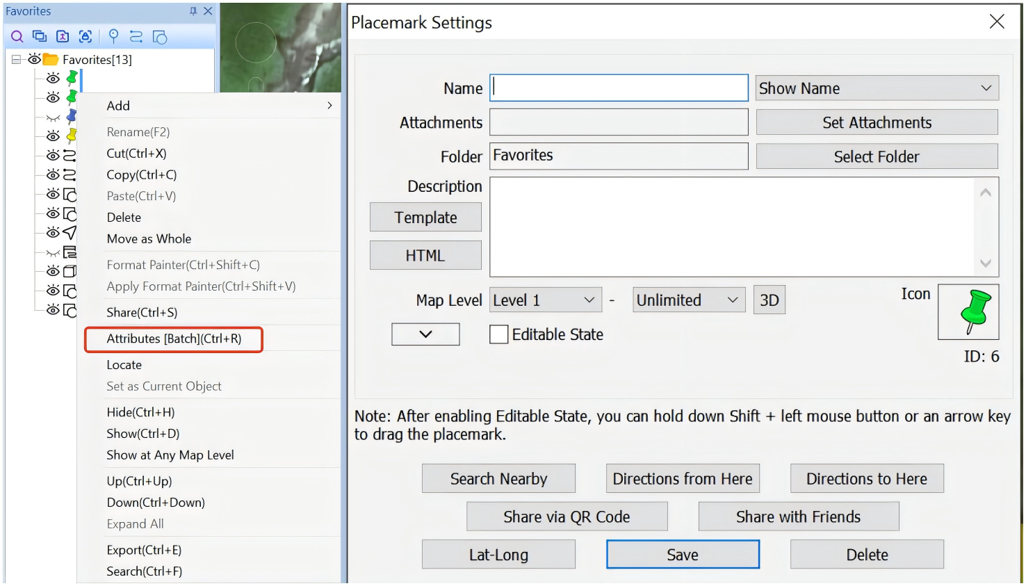
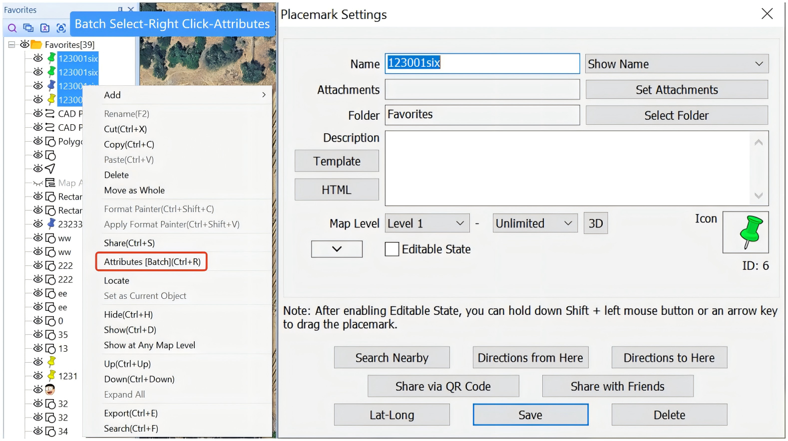
Step 1: Select the required placemarks, right-click on them, and select [Attributes] to go to the [Placemark Settings] dialog box.

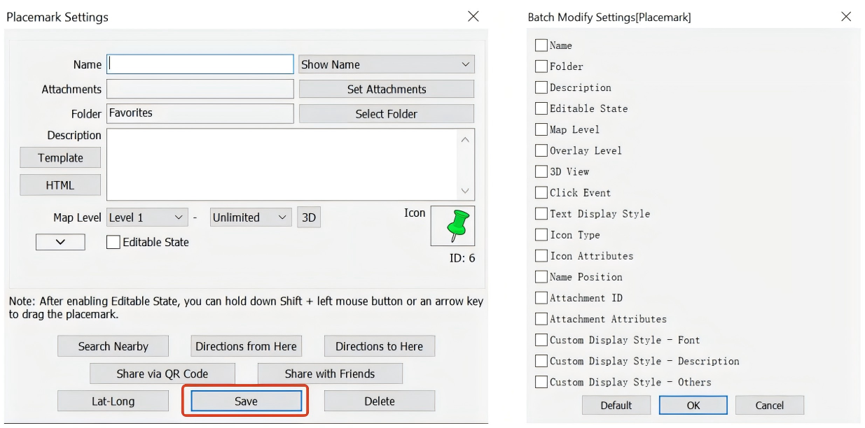
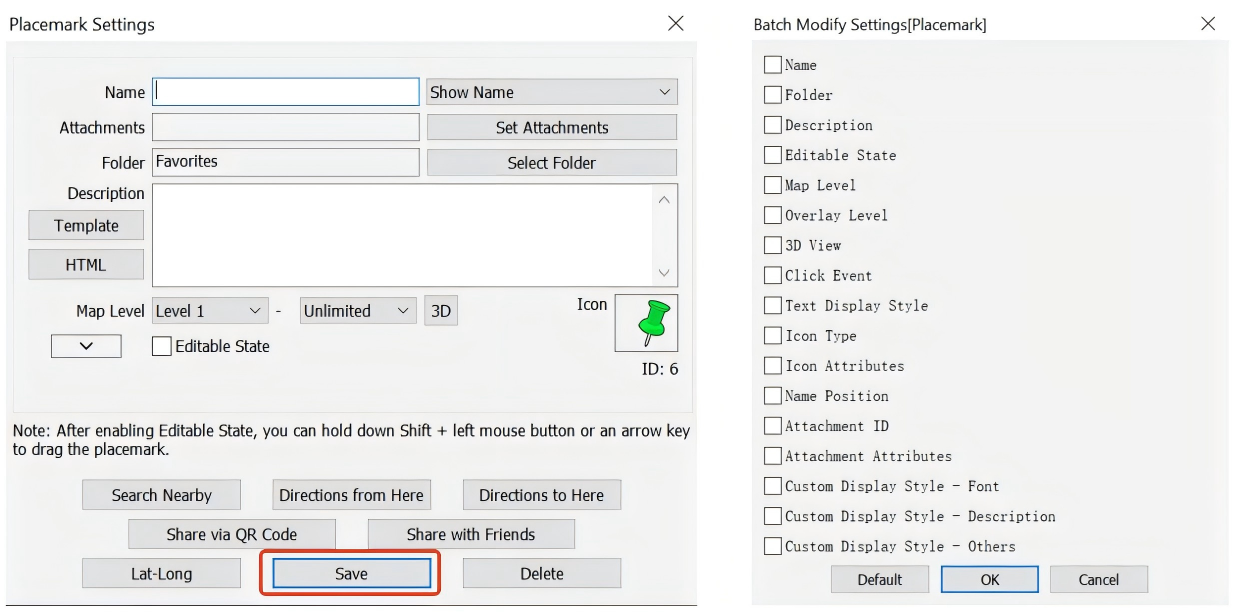
Step 2: Click [Save]. The [Batch Modify Settings] dialog box appears.

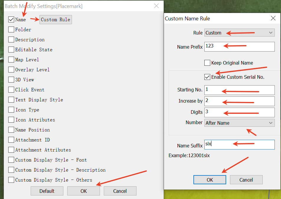
Step 3: Select [Name], and click the [Custom Rule] button that appears. In the [Custom Name Rule] dialog box, set the [Rule] parameter to [Custom], specify a prefix, select [Enable Custom Serial No.] and set the starting value, increment, total number of digits, and position for serial numbers, and specify a suffix. Then, click [OK].

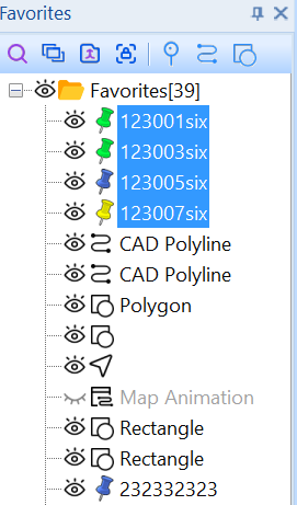
The selected placemarks are renamed based on the rule you set, as shown in the following figure:

image-20260715113851660

2) Replace part of text in multiple names

Step 1: Select the required placemarks, right-click on them, and select [Attributes] to go to the [Placemark Settings] dialog box.

image-20260715113933630

Step 2: Click [Save]. The [Batch Modify Settings] dialog box appears.

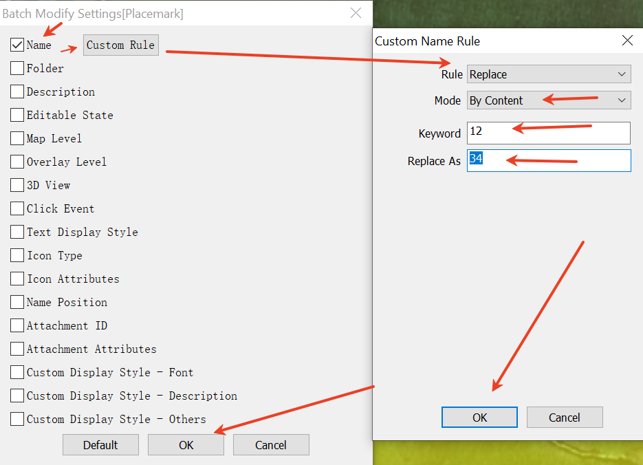
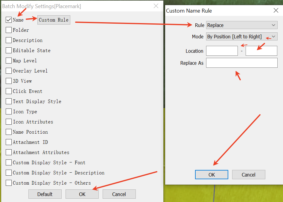
Step 3: Select [Name], and click the [Custom Rule] button that appears. In the [Custom Name Rule] dialog box, set the [Rule] parameter to [Replace]. Then, you can locate the part of text by content or by position. In this example, the [Mode] parameter is set to [By Content]. Specify the part of text to be replaced in the [Keyword] field and the intended content in the [Replace As] field. Then, click [OK].

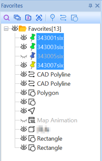
The selected placemarks are renamed based on the settings, as shown in the following figure:

image-20260715114155973

When the text in the placemark names is totally different, you can replace part of the text by position. In this case, set the [Mode] parameter to [By Position], and set the location range as needed.

In QubiMap, you can split one or more shapes into several parts. You can also perform topological operations such as union (‌), intersection (‌), difference (‌), and XOR (‌) on shapes. The latter shape composition feature is only available to VIP users.

This article describes how to use the shape splitting and shape composition features on a PC. For information about how to use these features on a mobile device, see the help document “How to use the shape splitting and shape composition features on a mobile device“.

1. Shape splitting

1.1. Split a single shape

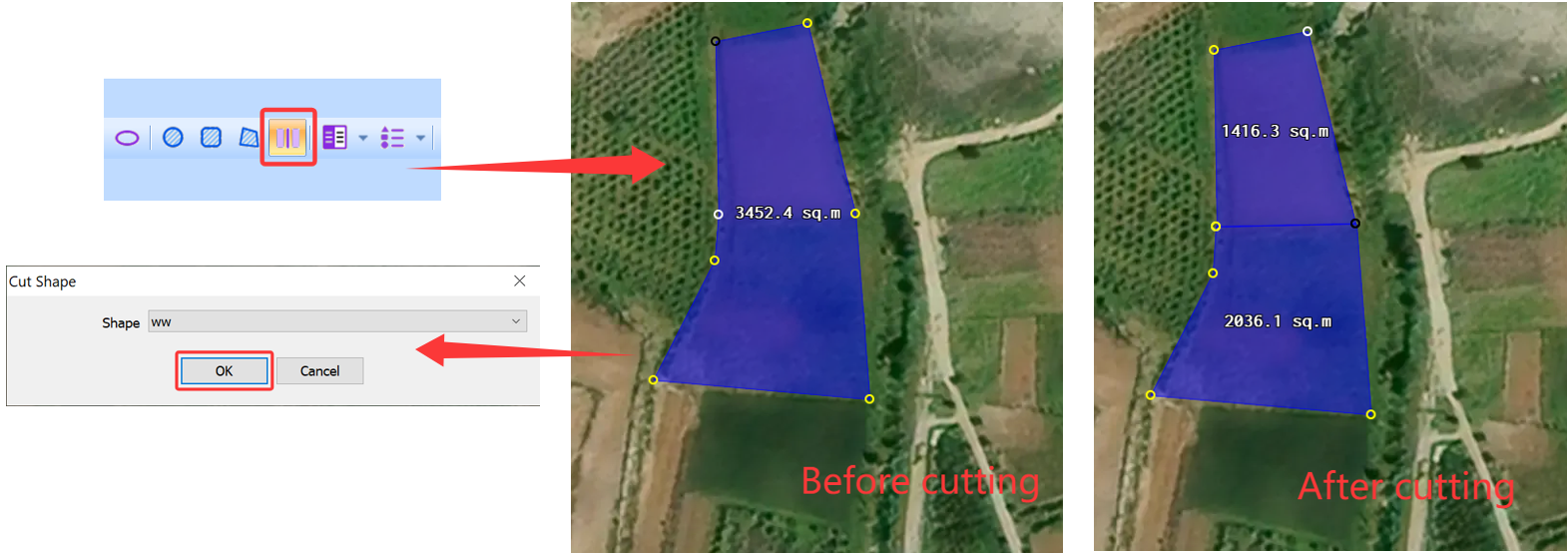
Find the required shape on the map, and click the Image 111 button in the toolbar to draw a line through the shape. Click on the map to start drawing, and double-click to finish drawing.

In the [Cut Shape] dialog box that appears, select the shape and then click [OK].

After cutting, the attributes of the shapes such as name and fill color remain unchanged, and the common edge is displayed.

image-20260714104917508

1.2. Split multiple shapes

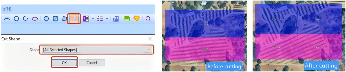
Find the required shapes on the map, and click the Image 111 button in the toolbar to draw a line through the shapes.

In the [Cut Shape] dialog box that appears, select [All Selected Shapes] and then click [OK].

After cutting, the attributes of the shapes such as name and fill color remain unchanged, and the common edges are displayed.

2. Shape composition

You can perform topological operations such as union (‌), intersection (∩), difference (-), and XOR (‌) for shape composition.

Operation Number of shapes Optimization option New shape attributes
Union (∪) ≥2 Optimize proximate points/Delete original shapes Number of vertices, number of regions, perimeter, and area
Intersection (∩) ≥2
Difference (-) 2
XOR (⊕) ≥2

2.1. Union (‌)

This operation is used to merge multiple shapes into a single shape. The attributes of the generated shape after merging such as name and fill color remain the same as the first shape before merging. If the original shapes intersect or share common edges, the intersections or common edges are deleted.

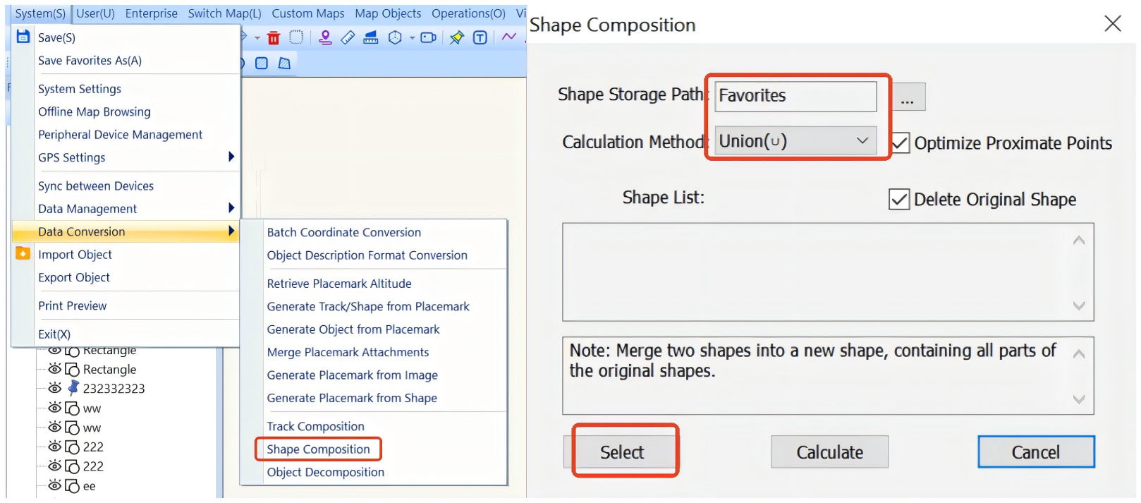
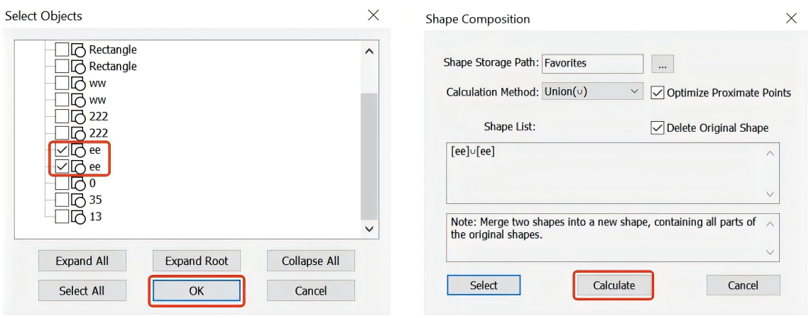
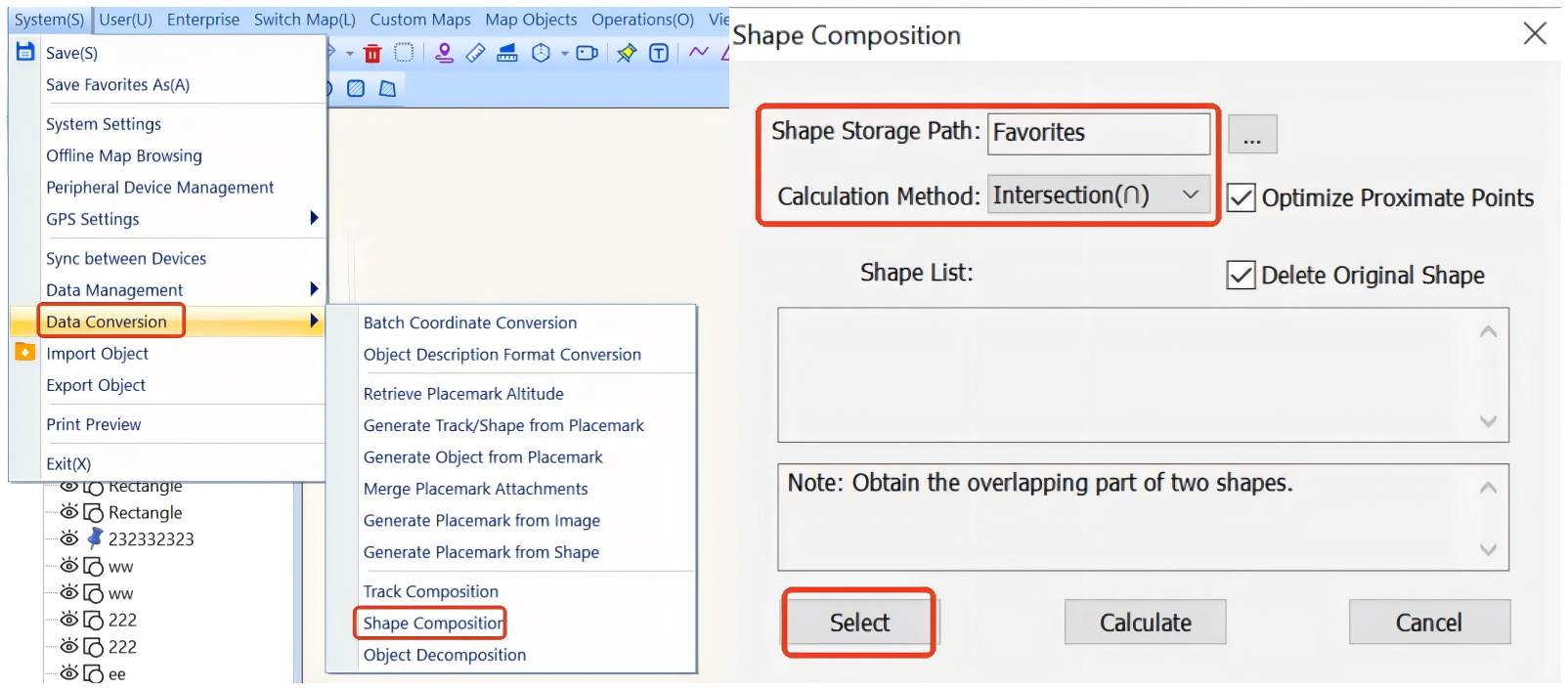
On the main UI, choose [System] > [Data Conversion] > [Shape Composition]. Specify a shape storage location, set the operation method to [Union (∪)], and click [Select] to select shapes.

Optimize Proximate Points: This option can prevent small gaps from appearing when you import and export the generated shape. We recommend that you keep the default settings.

Delete Original Shapes: The original shapes are not retained after merging. We recommend that you keep the default settings.

After you select the shapes to merge, click [OK] → [Calculate].

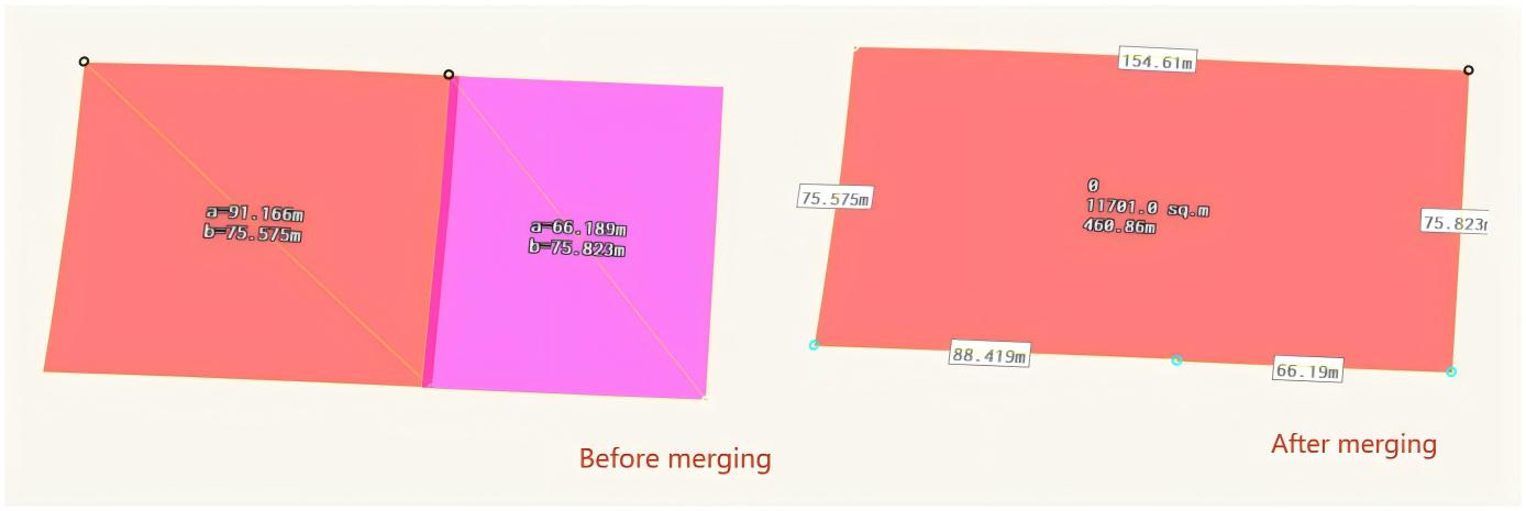
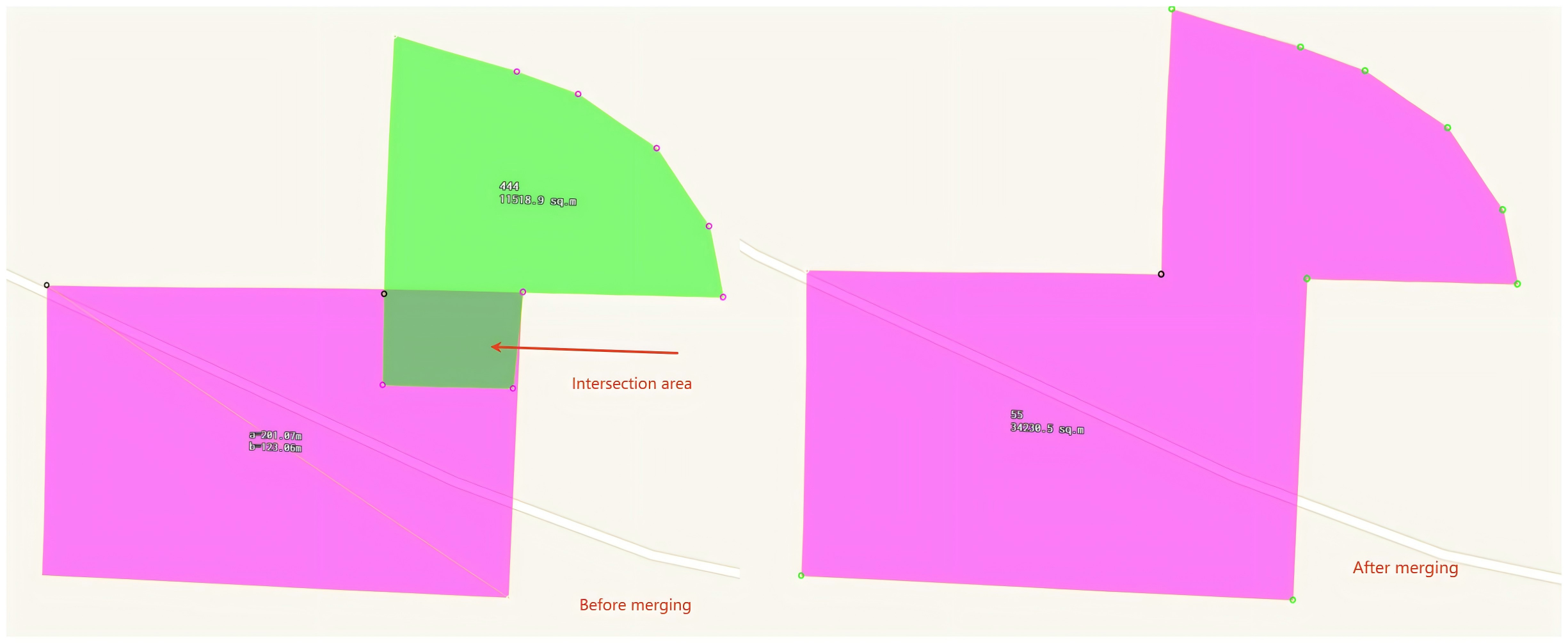
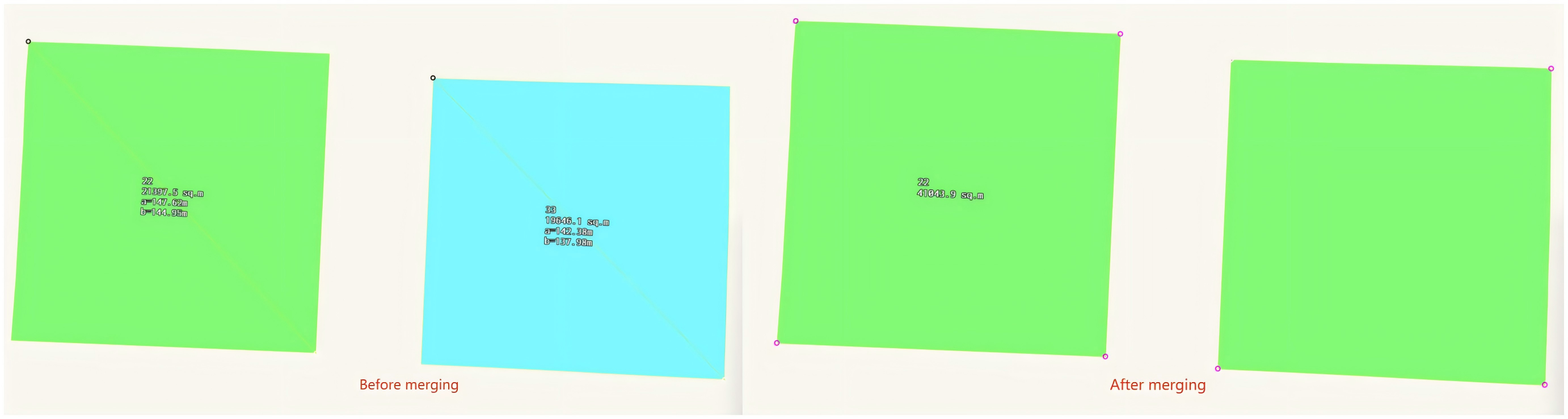
Effects after merging:

① If the original shapes share common edges, the common edges are deleted. The attributes of the generated shape after merging such as name and fill color remain the same as the first shape before merging.

② If the original shapes intersect, the intersections are deleted. The attributes of the generated shape after merging such as name and fill color remain the same as the first shape before merging.

③ If the original shapes are not adjacent, their relative positions remain unchanged. The name of the generated shape after merging remains the same as the first shape before merging, and the fill pattern changes to the system default value.

2.2. Intersection (∩)

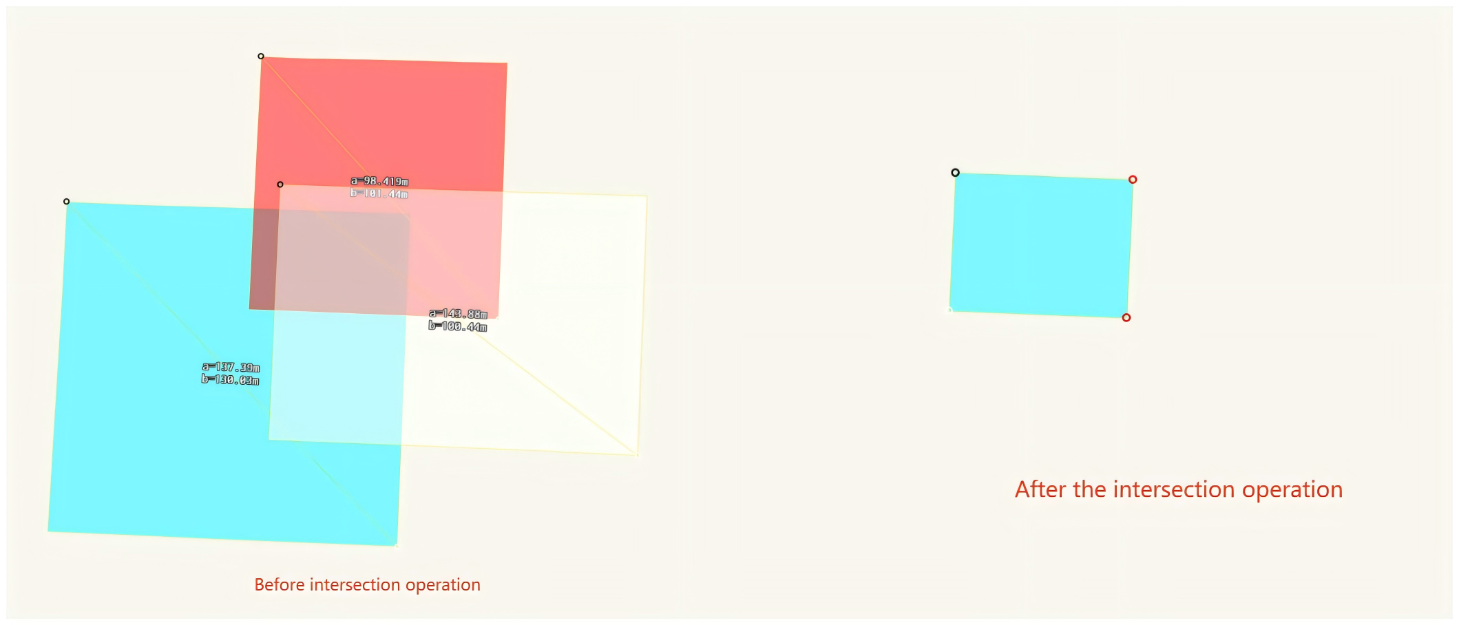
This operation is used to obtain the overlapping part of multiple shapes. You cannot select the shapes that do not intersect for this operation.

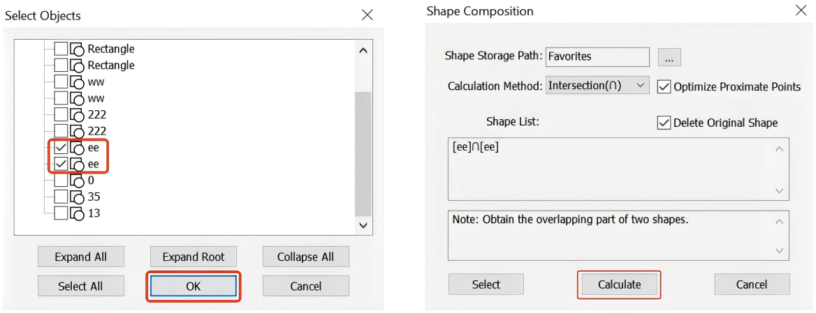
On the main UI, choose [System] > [Data Conversion] > [Shape Composition]. Specify a shape storage location, set the operation method to [Intersection (∩)], and click [Select] to select shapes.

After you select the shapes, click [OK] → [Calculate].

Only the overlapping part of shapes are retained, as shown in the following figure:

2.3. Difference (-)

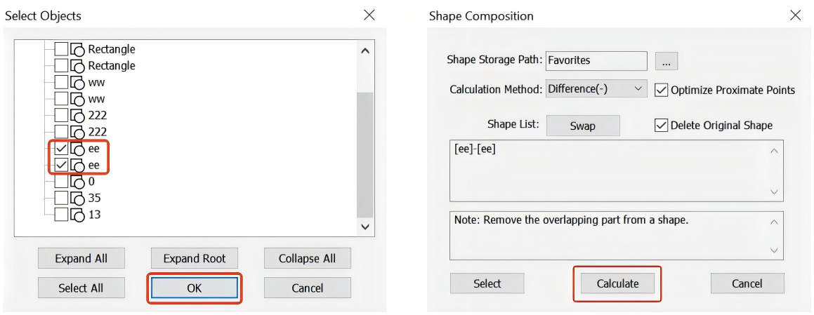
This operation is used to remove the overlapping part of two shapes from the first shape. That is, only the non-overlapping part of the first shape is retained.

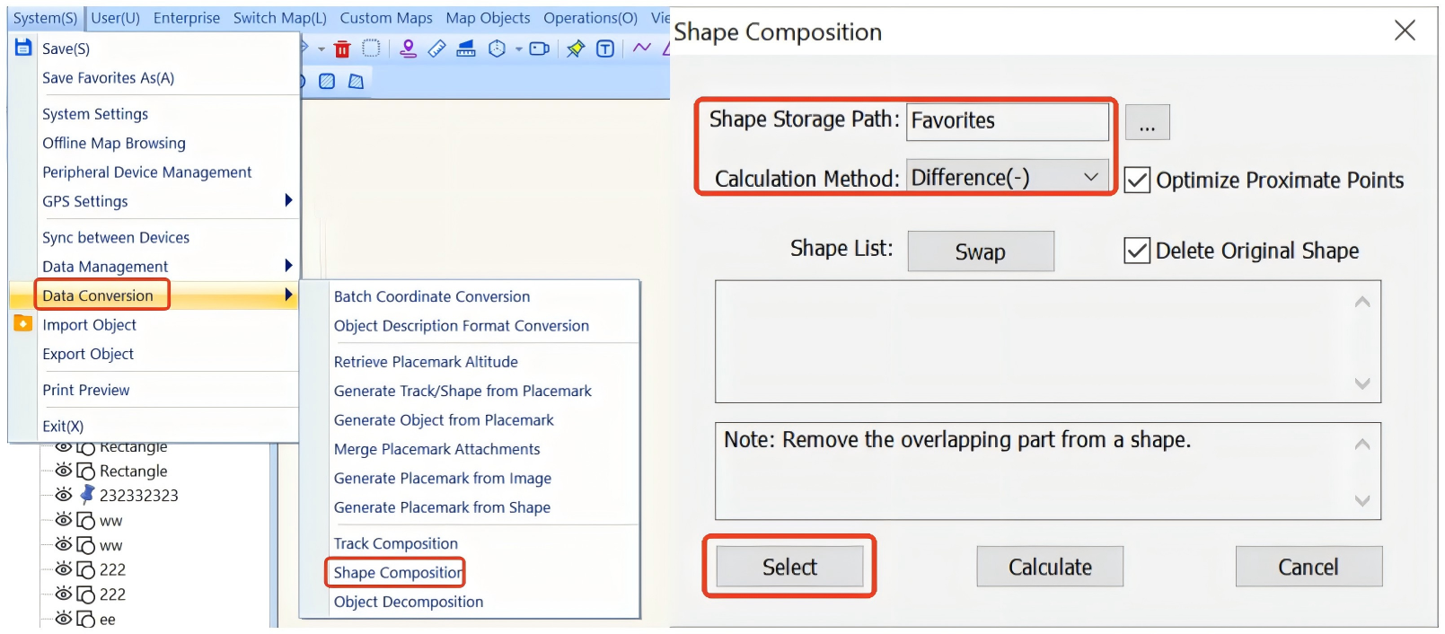
On the main UI, choose [System] > [Data Conversion] > [Shape Composition]. Specify a shape storage location, set the operation method to [Difference (-)], and click [Select] to select shapes.

After you select the shapes, click [OK] → [Calculate].

Note: You can adjust the order of shapes in the shape list.

Examples:

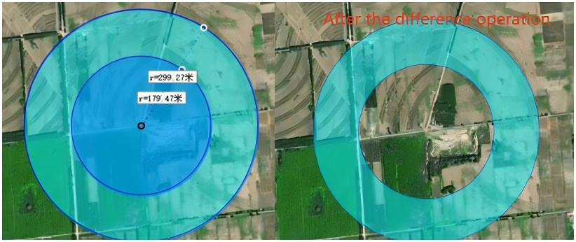
① Perform this operation on two circles, with the large circle as the first shape (namely, remove the small circle from the large circle). An annular circle is obtained, as shown in the following figure:

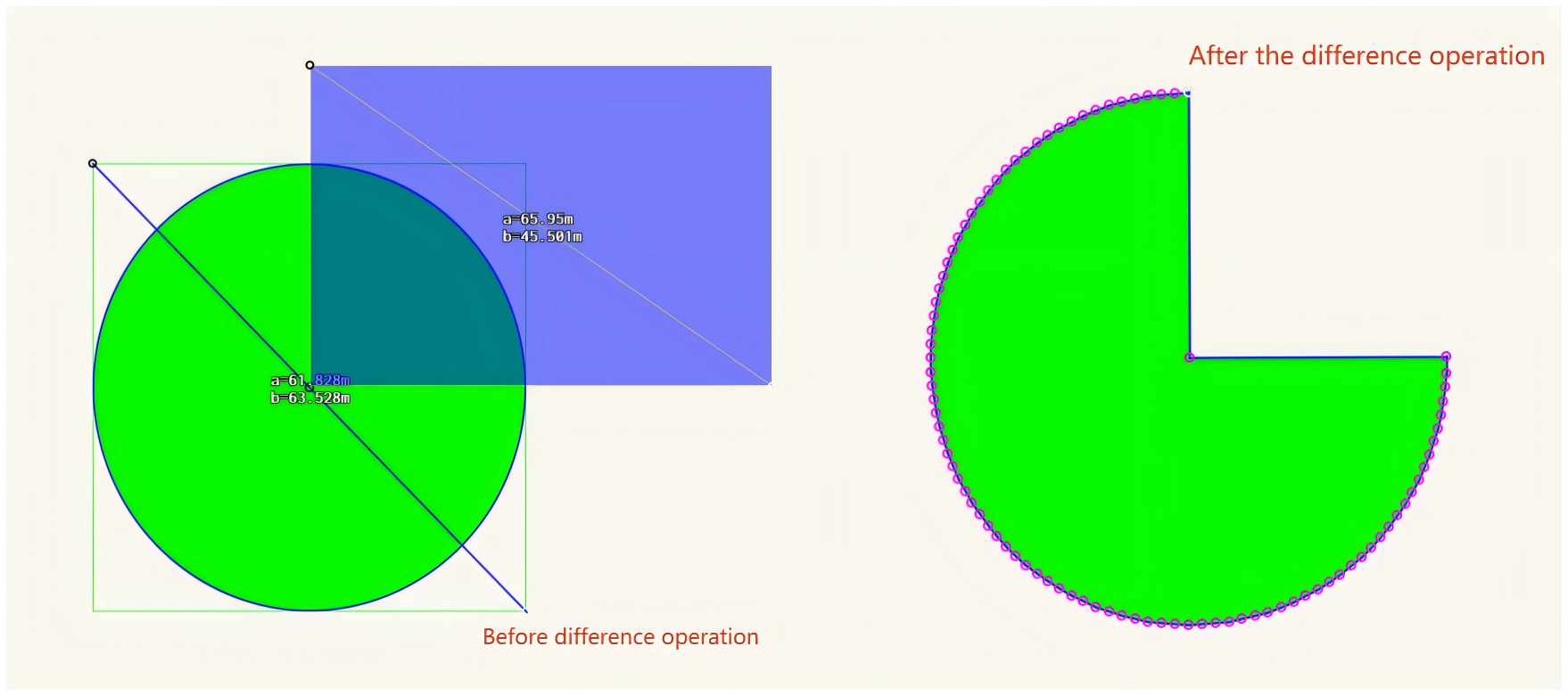
② Perform this operation on a circle and a rectangle, with the circle as the first shape. Only the non-overlapping part of the circle is retained, as shown in the following figure:

2.4. XOR (‌)

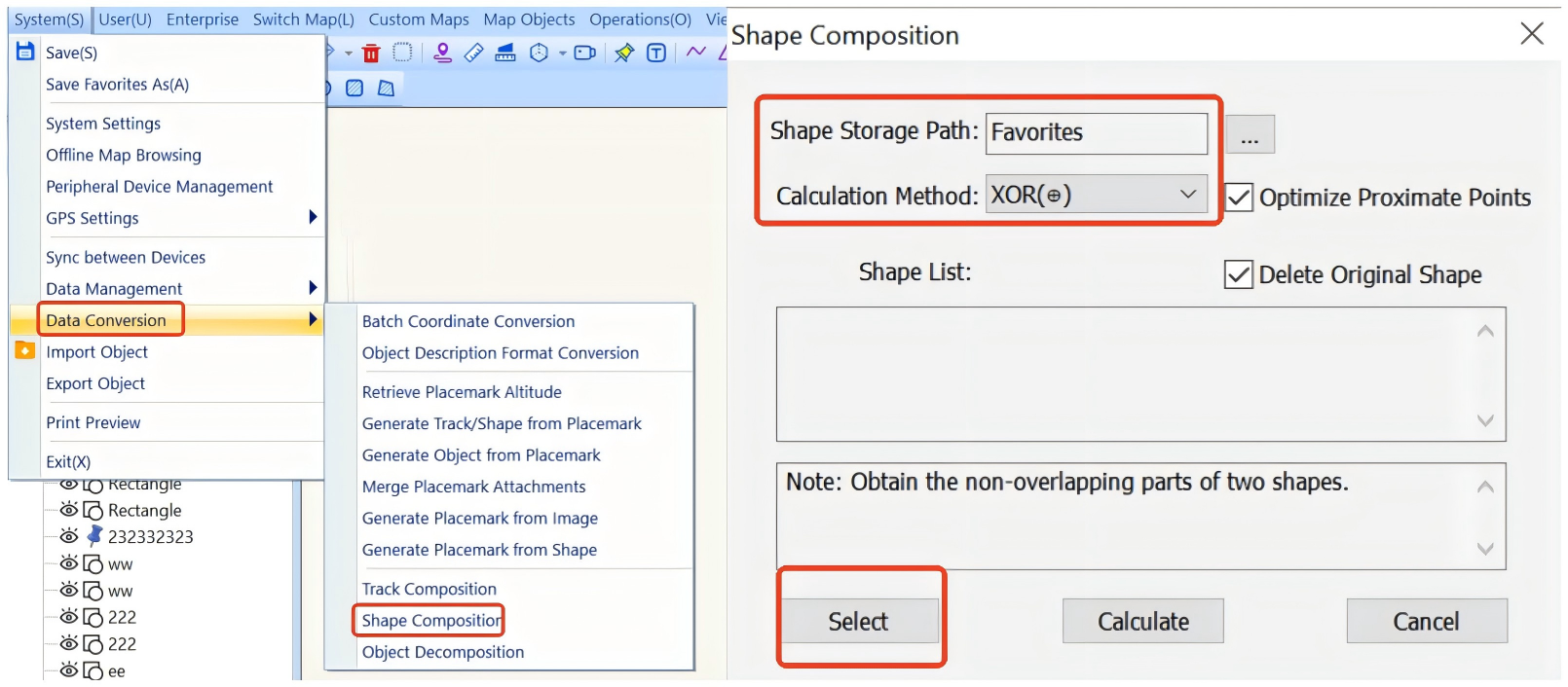
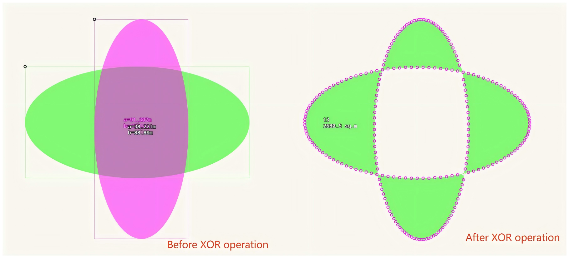
This operation is used to remove the overlapping parts of multiple shapes and retain the rest parts as a new shape. If the selected shapes that do not intersect, the result of this operation is the same as the union operation.

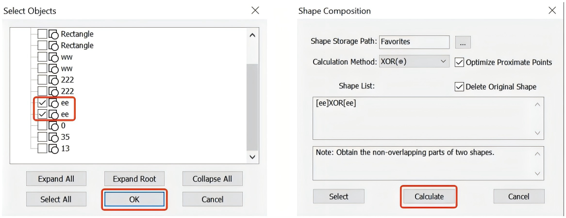
On the main UI, choose [System] > [Data Conversion] > [Shape Composition]. Specify a shape storage location, set the operation method to [XOR (‌)], and click [Select] to select shapes.

After you select the shapes, click [OK] → [Calculate].

Example: Perform this operation on two intersected ellipses. The overlapping part is removed, and the rest parts are retained as a new shape, as shown in the following figure:

In QubiMap, you can view the profile (section) of a track and calculate the fill or cut volume and area of a shape. These features are only available to SVIP users.

This article describes how to use these features on a PC. For information about how to use these features on a mobile device, see the help document “How to view the track profile and calculate the cut or fill volume and area on a mobile device“.

1. View the track profile (section)

On the main UI, click the 3D button to enter 3D mode.

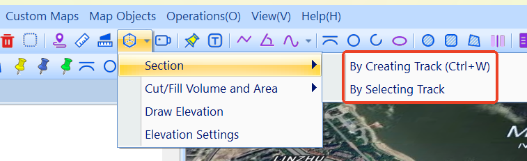
Click the Image 12 button and select [Section]. You can create a track or select an existing track to view its profile.

By Creating Track: Draw a track on the map. Click to draw, and double-click to finish drawing. Then, the sectional view is demonstrated.

By Selecting Track: Select a track from your favorites. Click the Image 12 button and choose [Section] > [By Selecting Track] to select a track, and then click [OK].

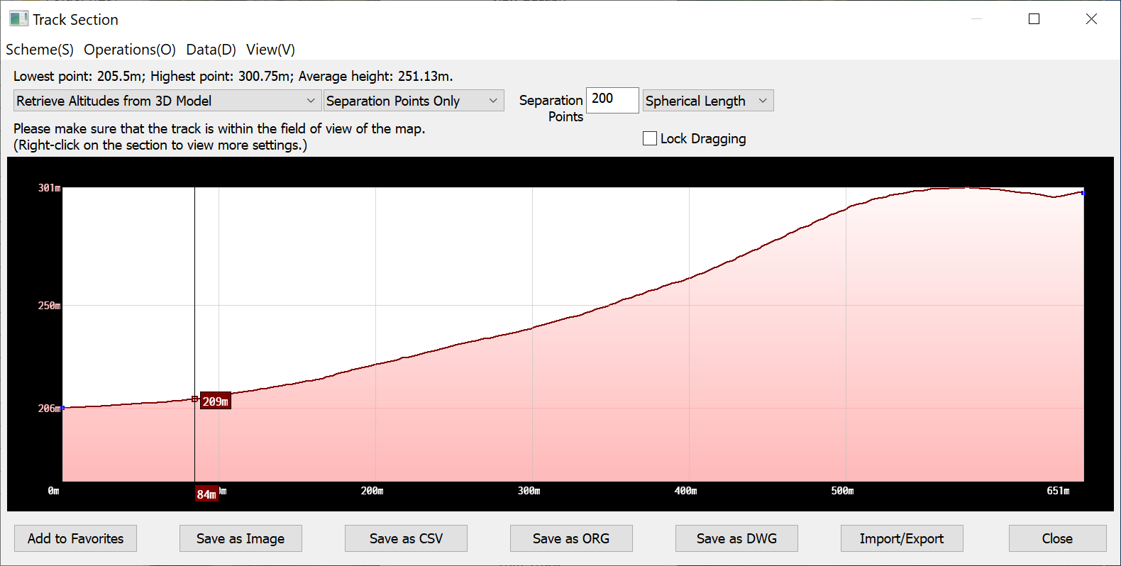
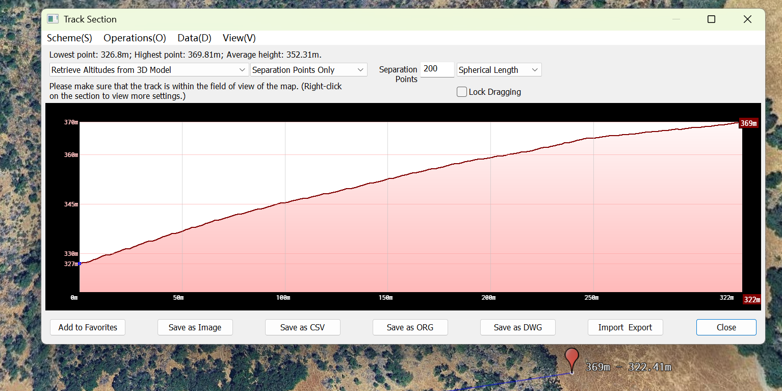
The sectional view is demonstrated.

image-20260715093303424

In the [Track Section] dialog box, you can view the elevations of the lowest and highest points and the average height of the track. You can select one of the following methods to retrieve the elevation data: [Retrieve Altitudes from Track Points], [Retrieve Altitudes from Elevation Database], [Retrieve Altitudes from 3D Model], and [Combine Heights of Track Points & Terrain]. You can also set the number of separation points and specify whether to include track points. The generated track profile can be saved as an image, CSV, ORG, or DWG file.

2. Calculate the fill or cut volume and area

This feature is commonly used for the earthwork in building, road, and bridge construction.

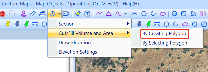
On the main UI, click the 3D button to enter 3D mode. Then, click the Image 12 button and select [Cut/Fill Volume and Area]. You can create a shape or select an existing shape for calculation.

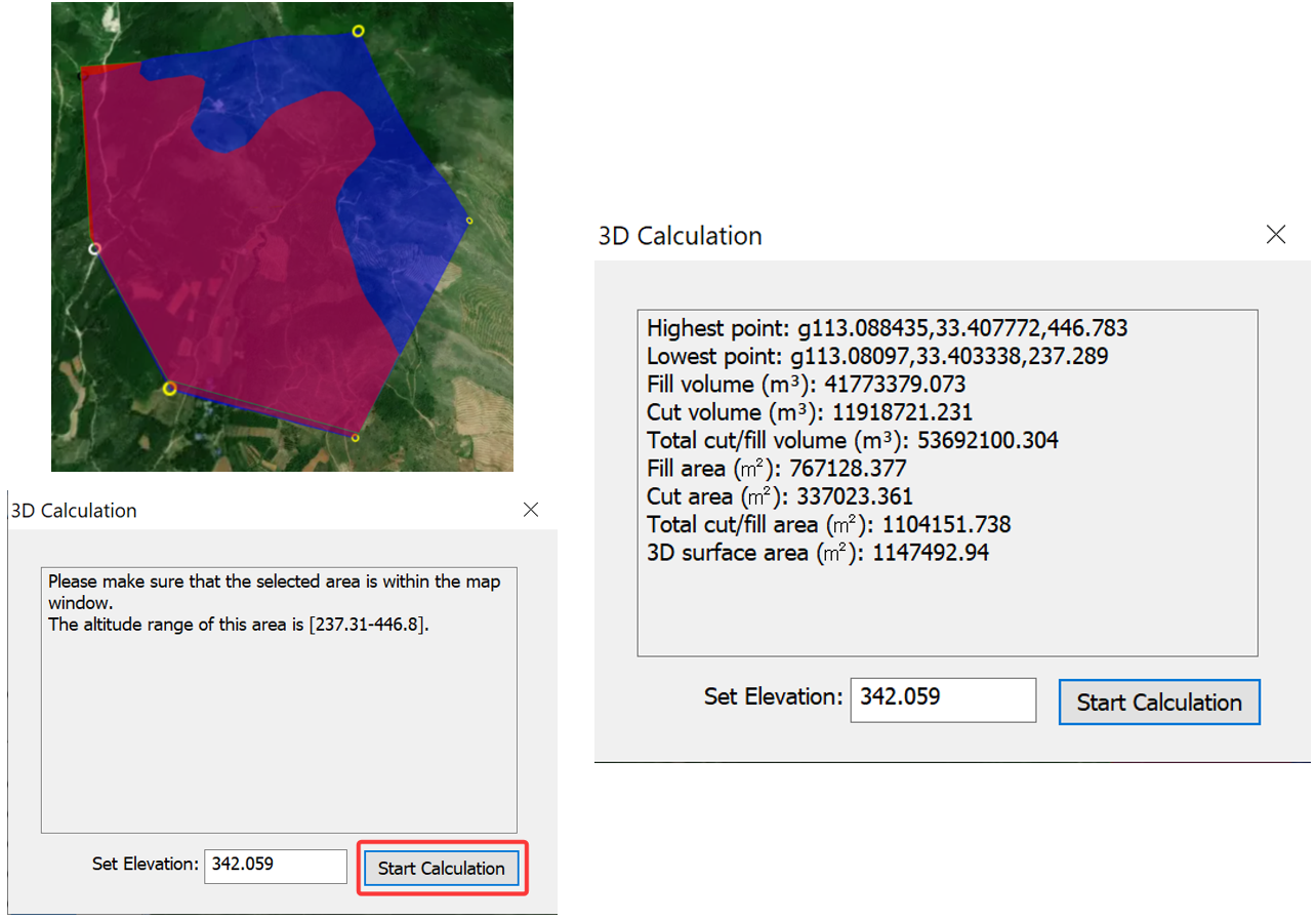
By Creating Polygon: Draw a polygon on the map. Click to draw, and double-click to finish drawing. The [3D Calculation] dialog box appears. You can set the elevation and click [Start Calculation]. The cut/fill volume and area within this region is automatically calculated.

image-20260715094104578

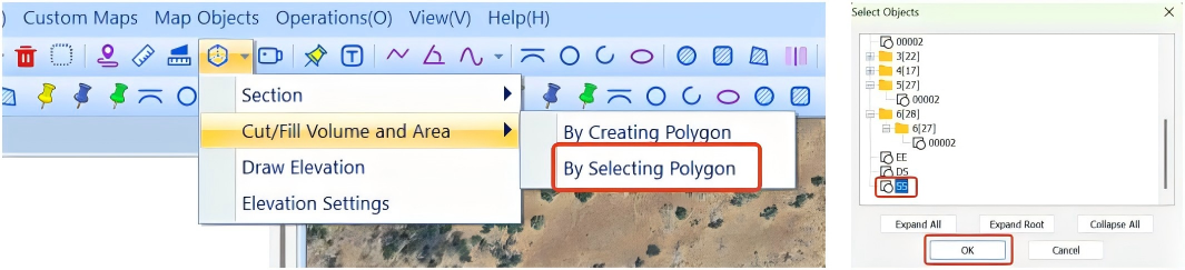
By Selecting Polygon: Select a shape from your favorites. Click the Image 12 button and choose [Cut/Fill Volume and Area] > [By Selecting Polygon] to select a shape, and then click [OK].

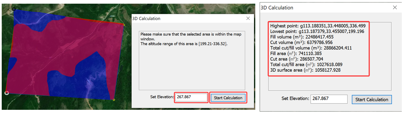
Then, you can set the elevation and click [Start Calculation].

P2P sync is used to establish a connection and synchronize favorites data and placemark attachments between devices.

1. Sync data from a mobile device to PC

1) Establish a connection

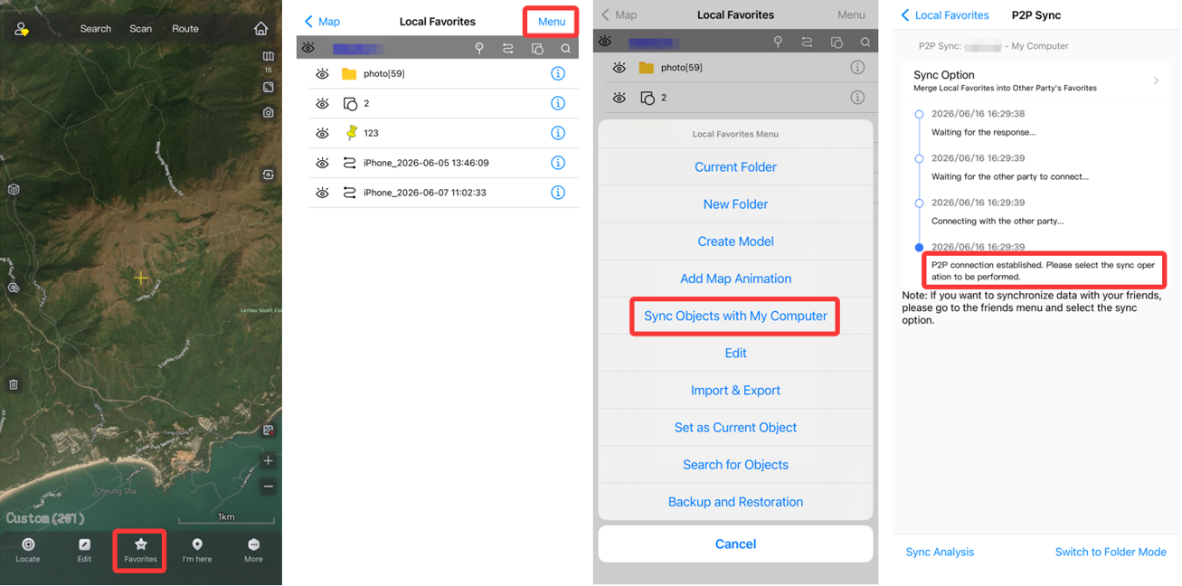
After you log in to your account on your mobile device, Tap [Favorites] -> [Menu] -> [Sync Objects with My Computer]. On the [P2P Sync] page, the connection status is displayed.

If the P2P connection is established, you can perform the sync operation.

If the connection fails, please check if the network on your mobile device or PC is available. To ensure connection stability, we recommend that the two devices be connected to the same network.

image-20260715172505328

2) Sync objects in the favorites

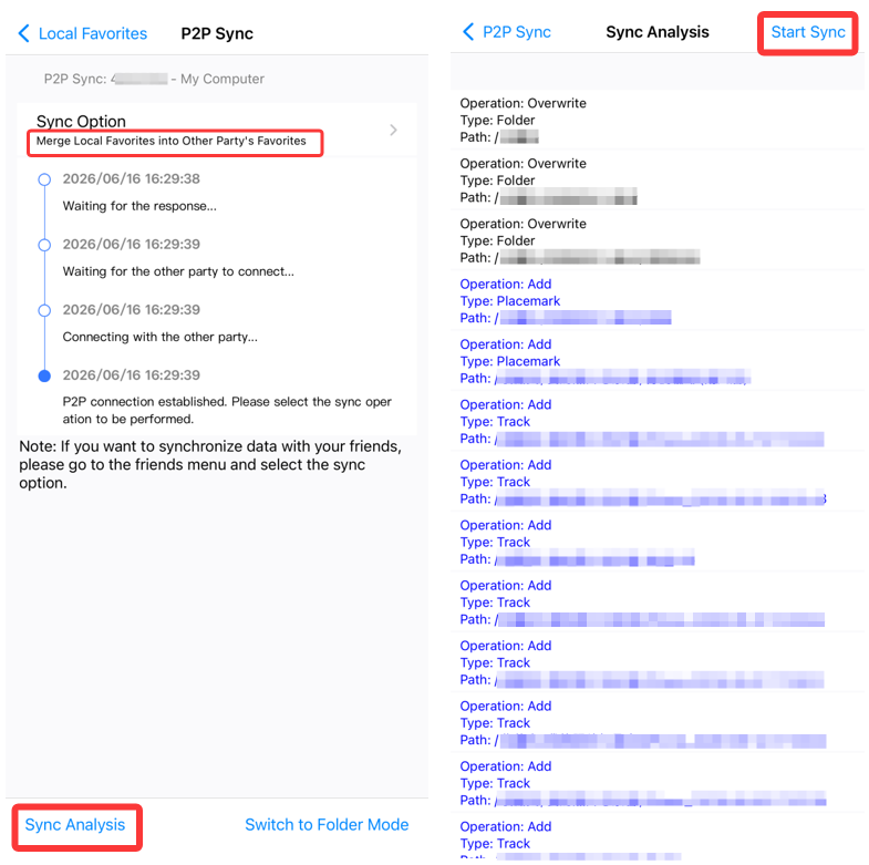
You can select one of the following sync options:

① Merge Local Favorites into Other Party’s Favorites: The same objects are overwritten, and the additional objects on the mobile device are added to the PC.

② Overwrite Other Party’s Favorites with Local Favorites: The same objects on the PC are overwritten, the additional objects on the PC are deleted, and the additional objects on the mobile device are added to the PC.

③ Merge Local Attachments into Other Party’s Attachment Library: Used to sync attachments. The additional attachments on the mobile device are added to the PC.

We recommend that you select [Merge Local Favorites into Other Party’s Favorites]. Then, Tap [Sync Analysis]. After the analysis is completed, Tap [Start Sync].

image-20260616165614111

If you need to sync a specified folder, tap [Switch to Folder Mode]. For more details, see the help document How to sync a folder in the favorites.

3) Sync attachments

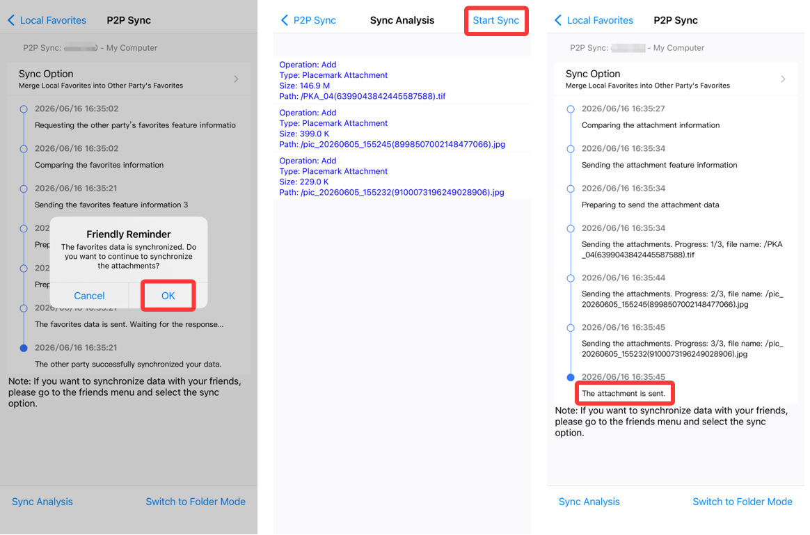
After the objects in the favorites are synced, if the objects have attachments, the system will remind you to sync the attachments.

If you do not need to sync the attachments, tap [Cancel].

If you need to sync the attachments, tap [OK] -> [Start Sync].

image-20260616170203441

2. Sync data from a PC to mobile device

After you log in to your account on your PC, choose [User] > [Sync with Mobile Phone].

For detailed steps, refer to the previous section “1. Sync data from a mobile device to PC”.

In addition to the built-in maps, you can add custom maps to QubiMap, including online maps and aerial images. Currently, the supported aerial image formats include JPEG, PNG, TIFF, and IMG.

This article describes how to import aerial images and set map overlays.

1. Create a custom map layer

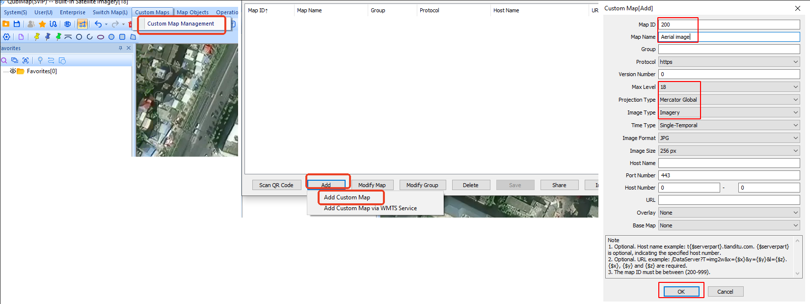
On the main UI of QubiMap on your PC, Choose [Custom Maps] > [Custom Map Management].
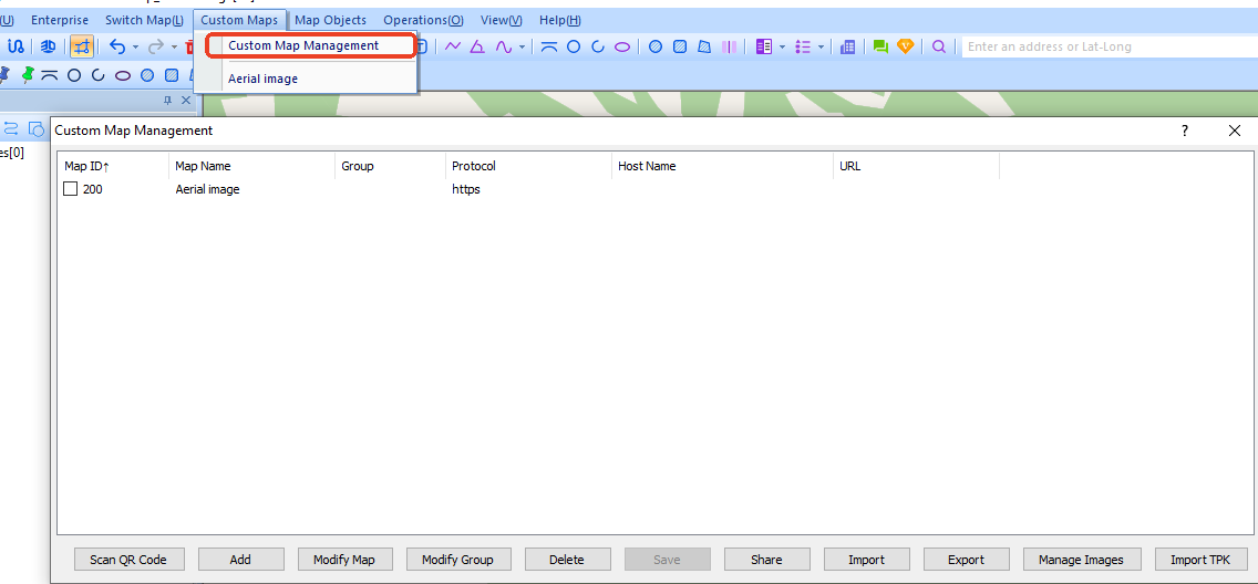
image-20260611155458230

In the [Custom Map Management] dialog box, click [Add] and select [Add Custom Map] from the drop-down list. In the dialog box that appears, set the parameters and click [OK].
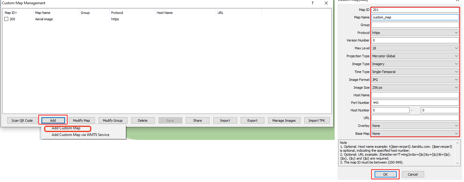
image-20260611160037199

★ Parameters:

① Map ID: a unique ID number assigned to each custom map, ranging from 200 to 999.

② Map Name: the name of the map displayed in the custom map list.

③ Max Level: the highest display level of this map. Set a value higher than the actual level of the aerial images.

④ Projection Type: Select [Mercator (Global)]. It must match the projection type of the base map to prevent misalignment.

⑤ Time Type: Select [Single-Temporal] or [Multi-Temporal (Historical Images)] as needed. For more information about multi-temporal images, see the help document “How to add multi-temporal (historical) images to a custom map”.

⑥ For other parameters, you can keep the default values.

2. Import aerial images to the custom map

In the [Custom Map Management] dialog box, select the custom map and click [Manage Images].

You can import aerial images by using the following methods:
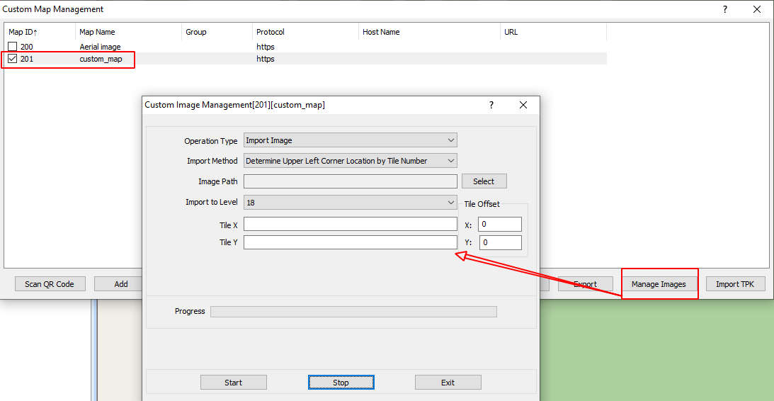
image-20260611161224188

1) Determine Range via Lat-Long

If aerial images contain the lat-Long information in the upper-left and lower-right corners, you can use this method to import them. This method ensures precise alignment with the actual location.

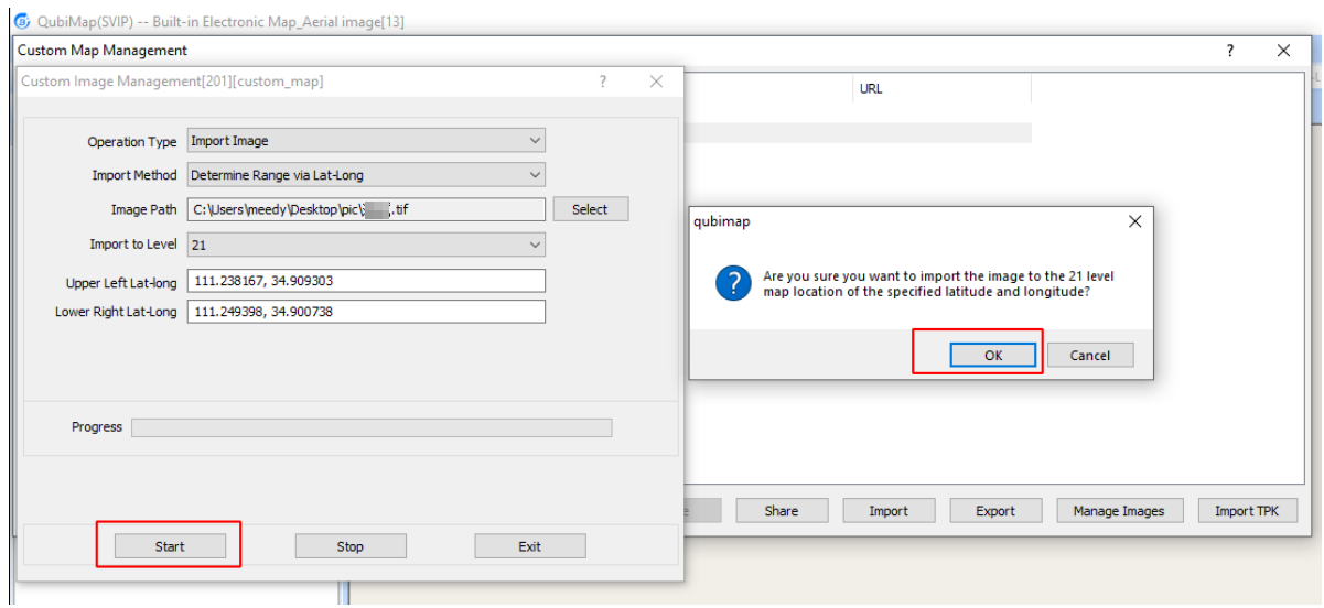
In the [Custom Image Management] dialog box, Select [Import Image] for the [Operation Type] parameter, select [Determine Range via Lat-Long] for the [Import Method] parameter. Then, click the [Select] button next to the [Image Path] field.
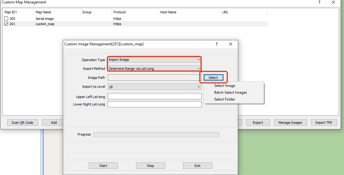
image-20260611161505408

The following options are available:

Select Image: Select a single aerial image to import.

Batch Select Images: Select multiple aerial images to import at a time.

Select Folder: Select all aerial images from an entire folder to import.

In this example, Select [Select Image]. Select the aerial image you want to import and click [Open].

The system automatically detects the display level based on the image resolution and lat-Long information in the upper-left and lower-right corners. You do not need to set the [Import to Level], [Upper Left Lat-Long], and [Lower Right Lat-Long] parameters.
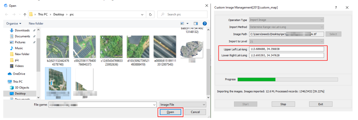
image-20260622153228118

Click [Start] to start importing.

image-20260622153450774

After the import is completed, click [Yes].
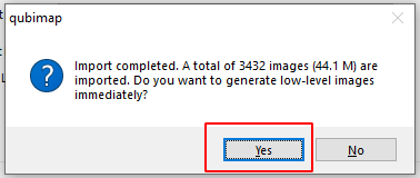
image-20260611165005446

2) Determine Range via TIFF/IMG File Coordinate Info

If aerial images contain the lat-Long information, you can use this method to import them. This method also ensures precise alignment with the actual location.

In the [Custom Image Management] dialog box, Select [Import Image] for the [Operation Type] parameter, select [Determine Range via TIFF/IMG File Coordinate Info] for the [Import Method] parameter. Then, click the [Select] button next to the [Image Path] field.
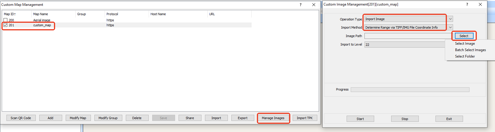
image-20260611170810876The following options are available:

Select Image: Select a single aerial image to import.

Batch Select Images: Select multiple aerial images to import at a time.

Select Folder: Select all aerial images from an entire folder to import.

In this example, Select [Select Image]. Select the aerial image you want to import and click [Open].

The system automatically detects the display level based on the image resolution. You do not need to set the [Import to Level] parameter.

Click [Start] to start importing.
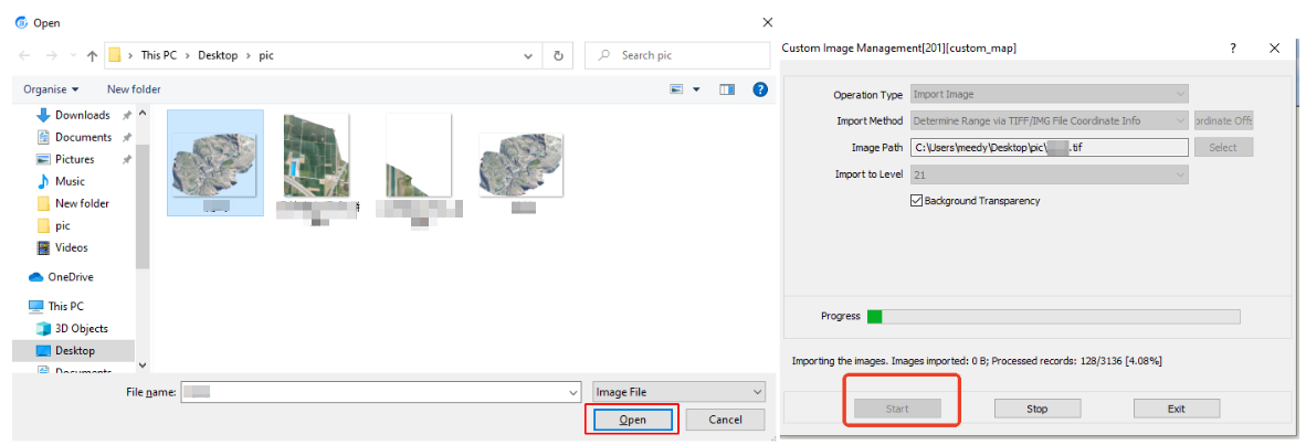
image-20260622153551694

After the import is completed, click [Yes].
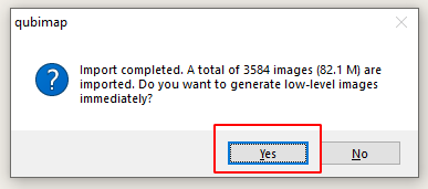
image-20260611171157867

On the main UI, switch to the custom map that is added, and you can view the imported aerial image.
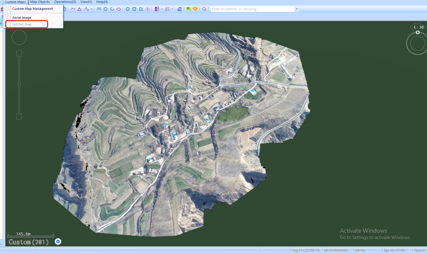
image-20260612085330976

3. Set an overlay layer

You can overlay the custom map onto a QubiMap built-in map. You can also overlay the road networks or other marker information onto the custom map. The projection types of the base map layer and overlay map layer must be consistent.

1) Set an overlay onto the custom map

In the [Custom Map Management] dialog box, select the custom map and click [Modify Map].
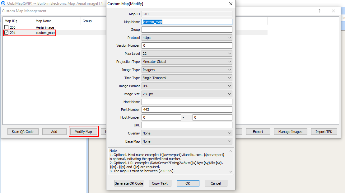
image-20260612085842631

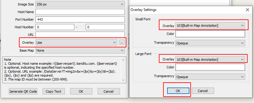
In the dialog box that appears, select [Use] for the [Overlay] parameter, and click the image-20240409153037219 button.

In the [Overlay Settings] dialog box, select the required overlay map layers in both [Small Font] and [Large Font] sections. In this example, a road network layer is selected. Additionally, you can set the color and transparency as needed. Then, click [OK].
On the main UI, switch to the custom map, and you can view the overlaid road networks.
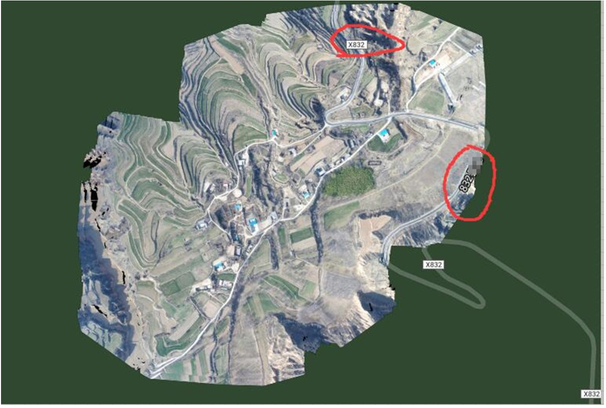
image-20260622153708633

2) Set a base map layer for the custom map

In the [Custom Map Management] dialog box, select the custom map and click [Modify Map]. In the dialog box that appears, select the required base map from the [Base Map] drop-down list, and click [OK].
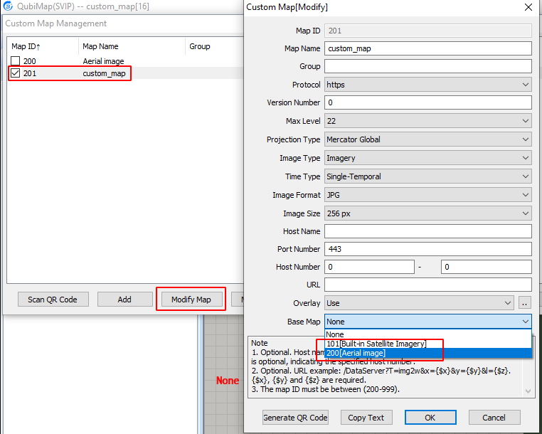
image-20260612093024319

On the main UI, switch to the custom map, and you can view the added base map.
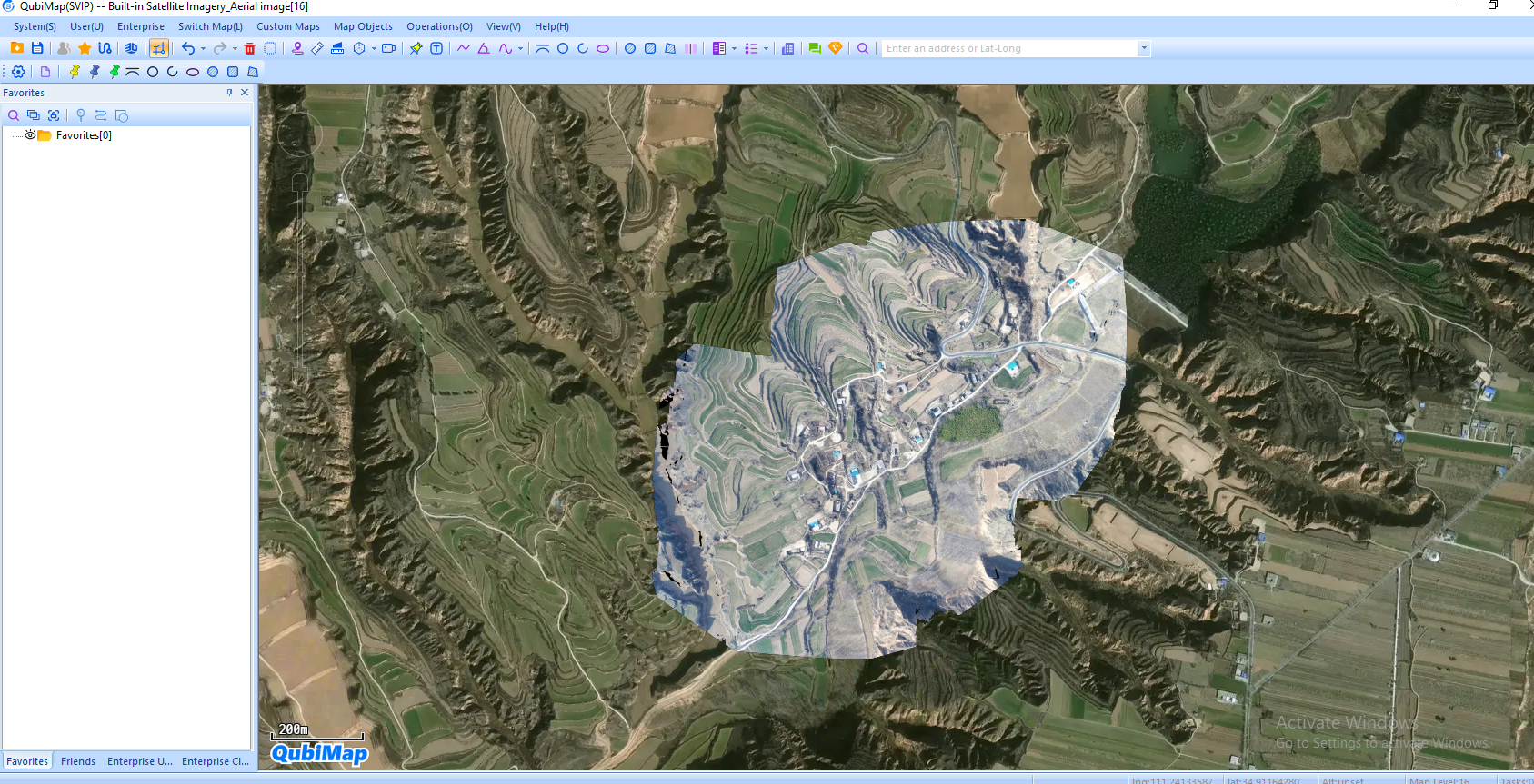
image-20260612095422615

4. Other methods to import aerial images

In addition to [Determine Range via Lat-Long] and [Determine Range via TIFF/IMG File Coordinate Info], you can also use the following methods to import aerial images to a custom map:

[Determine Location by Relation Point]: For more information, see the help document “Import custom maps by using relation points.”
[Import via Placemark Attachments Displayed on Map]: For more information, see the help document “Import custom maps by using placemark attachments displayed on the map.”
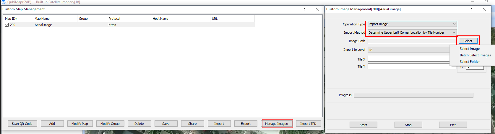
[Determine Upper Left Corner Location by Tile Number]: For more information, see the help document “Import custom maps by using tile IDs to determine upper left corner locations.”

In addition to the built-in maps, you can add custom maps to QubiMap, including online maps and aerial images. Currently, the supported aerial image formats include JPEG, PNG, TIFF, and IMG.

This article describes how to import aerial images in TIFF format.

1. Create a map layer

Before importing aerial images, you need to create a custom map layer.

Choose [Custom Maps] > [Custom Map Management]. In the [Custom Map Management] dialog box, click [Add] and select [Add Custom Map] from the drop-down list. In the dialog box that appears, set the map name, maximum level, projection type, and image type. No other parameters are required.

Max Level: Set a value higher than the actual level of the aerial images. Some aerial images may reach Level 21 or 22 in terms of resolution.

Projection Type: Select [Mercator Global]. It must match the projection type of the base map to prevent misalignment.

Image Type: Select [Imagery].

Time Type: Select [Single-Temporal] or [Multi-Temporal (Historical Images)] as needed. For more information about multi-temporal images, see the help document “How to add multi-temporal (historical) images to a custom map”.

Click [OK].

image-20260611145358518

2. Import images

You can import TIFF images onto the created custom map layer.

In the [Custom Map Management] dialog box, select the custom map and click [Manage Images]. Set the [Operation Type] parameter to [Import Image], and set the [Import Method] parameter to [Determine Range via TIFF/IMG File Coordinate Info].

Click [Select].

image-20260611145844356

The following options are available:

Select Image: Select a single TIFF aerial image to import.

Batch Select Images: Select multiple TIFF aerial images to import at a time.

Select Folder: Select all TIFF aerial images from an entire folder to import.

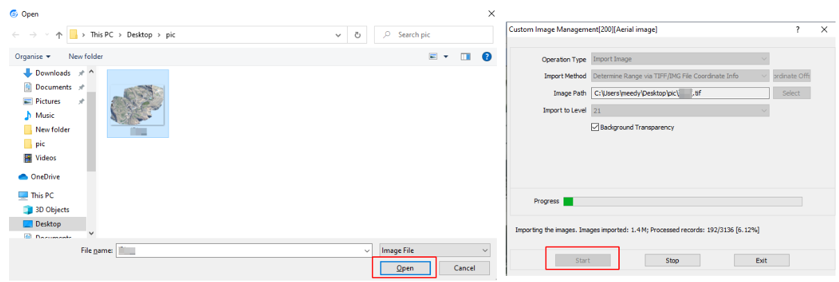
In this example, Select [Select Image]. Select the aerial image you want to import and click [Open].
The system automatically detects the display level based on the image resolution. You do not need to set the [Import to Level] parameter.

Click [Start] to start importing.

image-20260622152901407

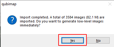
After the import is completed, click [Yes].

image-20260611150419319

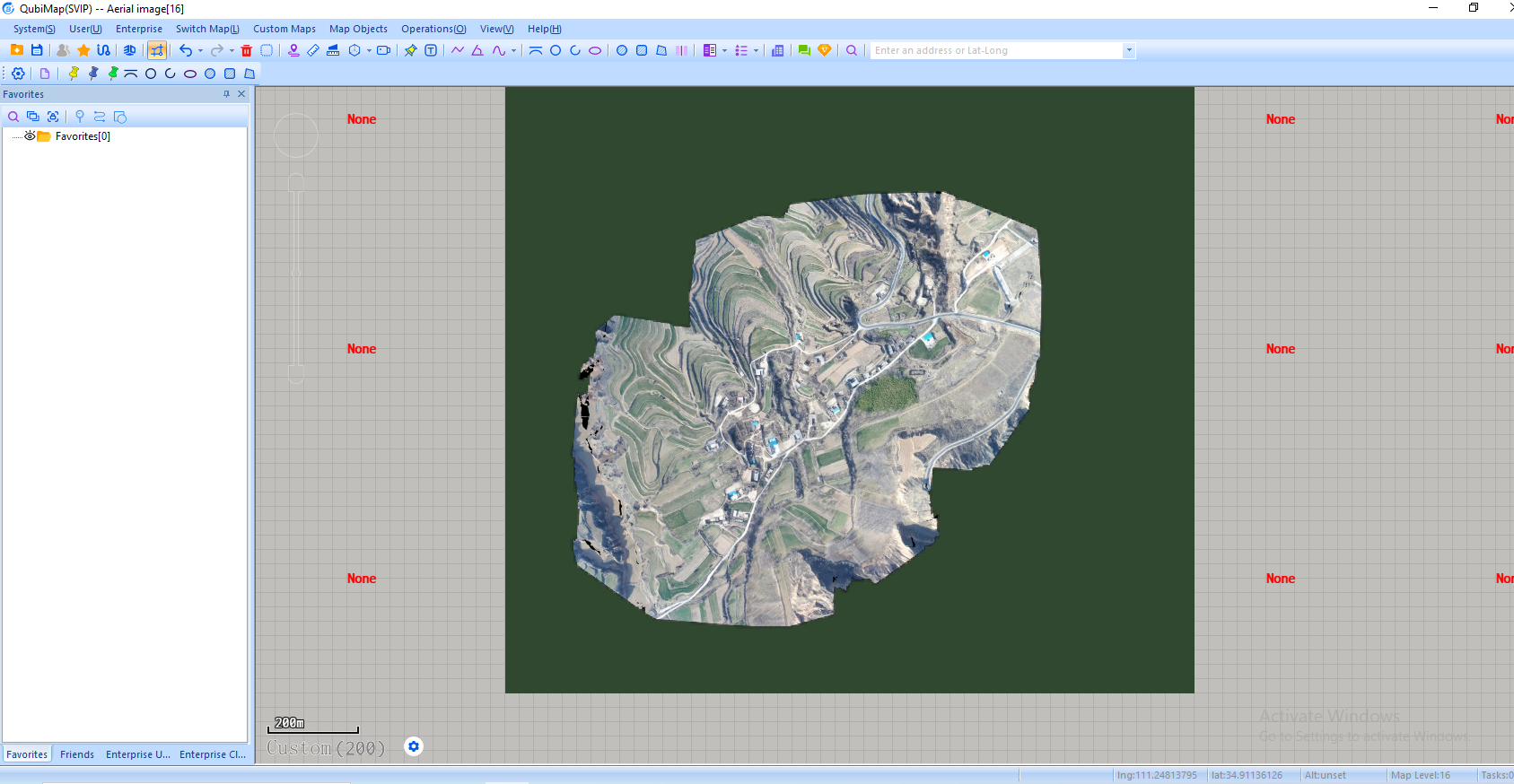
Switch to the custom map that is added, and you can view the imported aerial image.

image-20260611150747655

3. Set the custom map as a overlay layer

You can overlay the custom map onto a QubiMap built-in map. The projection types of both maps must be consistent.

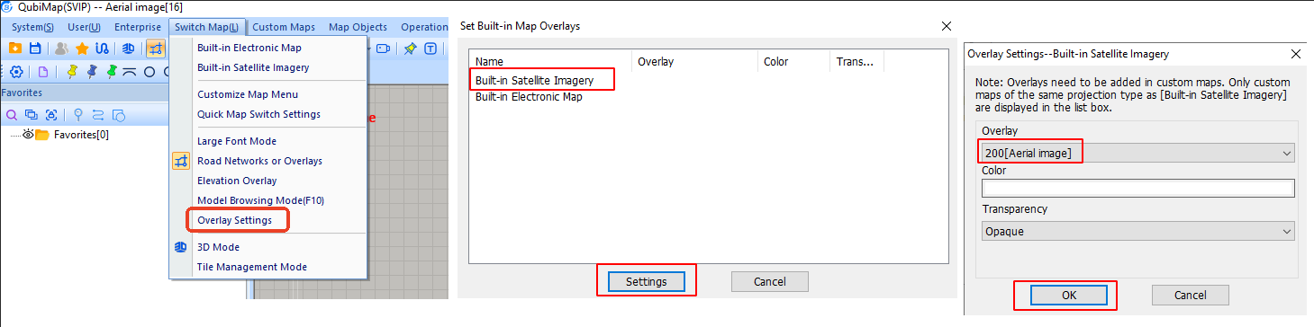
Choose [Switch Map] > [Overlay Settings]. Select a built-in map and click [Settings].

In the [Overlay Settings] dialog box, set the [Overlay] parameter to the added custom map, and click [OK].

image-20260611153524420

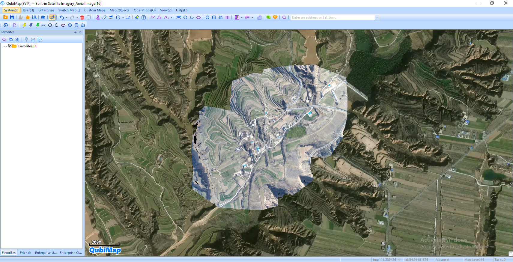
Switch to the built-in base map, and you can view the imported aerial image that is overlaid onto the built-in map.

image-20260611153730134

Note: For more information about map overlays, see the help document “How to import aerial images and set map overlays.”

Get ready to try QubiMap

Sign up for free trail and get started with QubiMap

Try Now